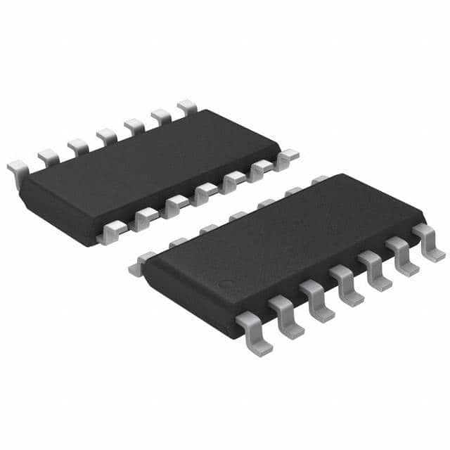
Viz Specifikace pro podrobnosti o produktu.

Encyclopedia Entry: 74HCT08S14-13
Product Overview
Category
The 74HCT08S14-13 belongs to the category of integrated circuits (ICs).
Use
This IC is commonly used in digital electronic circuits for performing logical AND operations.
Characteristics
- High-speed operation
- Low power consumption
- Wide operating voltage range
- Schmitt-trigger inputs for noise immunity
- Compatible with TTL and CMOS logic levels
Package
The 74HCT08S14-13 is available in a small outline integrated circuit (SOIC) package.
Essence
The essence of this product lies in its ability to provide reliable and efficient logical AND functionality in various digital applications.
Packaging/Quantity
Typically, the 74HCT08S14-13 is packaged in reels or tubes, containing a specific quantity of ICs per package.
Specifications
- Supply Voltage Range: 2V to 6V
- Input Voltage Range: 0V to VCC
- Output Voltage Range: 0V to VCC
- Operating Temperature Range: -40°C to +85°C
- Logic Family: HCT
- Number of Gates: 4
- Gate Type: AND
Detailed Pin Configuration
The 74HCT08S14-13 has a total of 14 pins, each serving a specific purpose. The pin configuration is as follows:
- Pin 1: Input A1
- Pin 2: Input B1
- Pin 3: Output Y1
- Pin 4: Ground (GND)
- Pin 5: Input A2
- Pin 6: Input B2
- Pin 7: Output Y2
- Pin 8: VCC (Supply Voltage)
- Pin 9: Input A3
- Pin 10: Input B3
- Pin 11: Output Y3
- Pin 12: Ground (GND)
- Pin 13: Input A4
- Pin 14: Input B4
- Pin 15: Output Y4
Functional Features
- Performs logical AND operation on four sets of input signals
- Outputs the result of each AND operation on respective output pins
- Schmitt-trigger inputs ensure noise immunity and reliable operation
- Wide operating voltage range allows compatibility with various systems
Advantages and Disadvantages
Advantages
- High-speed operation enables efficient processing of digital signals
- Low power consumption makes it suitable for battery-powered devices
- Wide operating voltage range provides flexibility in different applications
- Schmitt-trigger inputs enhance noise immunity, ensuring accurate logic operations
Disadvantages
- Limited number of gates (4) may restrict complex circuit designs
- Availability and pricing may vary depending on market demand
Working Principles
The 74HCT08S14-13 operates based on the principles of Boolean logic. It performs a logical AND operation on the input signals provided to its four sets of input pins. The output pins then reflect the result of each AND operation. The Schmitt-trigger inputs help eliminate noise and provide stable logic levels.
Detailed Application Field Plans
The 74HCT08S14-13 finds application in various digital electronic circuits where logical AND operations are required. Some common application fields include: - Microcontroller-based systems - Data communication networks - Industrial automation - Robotics - Signal processing
Detailed and Complete Alternative Models
There are several alternative models available that offer similar functionality to the 74HCT08S14-13. Some notable alternatives include: - 74LS08 - 74HC08 - SN74LS08 - CD4081
These alternative models can be considered based on specific requirements, availability, and compatibility with existing systems.
In conclusion, the 74HCT08S14-13 is a versatile integrated circuit that provides efficient logical AND functionality in digital electronic circuits. Its high-speed operation, low power consumption, and wide operating voltage range make it suitable for various applications. However, its limited number of gates and market availability may pose some limitations. Understanding its pin configuration, functional features, advantages, disadvantages, working principles, application field plans, and alternative models allows for informed decision-making when incorporating this IC into electronic designs.
Seznam 10 běžných otázek a odpovědí souvisejících s aplikací 74HCT08S14-13 v technických řešeních
Sure! Here are 10 common questions and answers related to the application of 74HCT08S14-13 in technical solutions:
Q: What is the 74HCT08S14-13? A: The 74HCT08S14-13 is a specific model of integrated circuit (IC) that combines four 2-input AND gates with Schmitt-trigger inputs.
Q: What is the purpose of the Schmitt-trigger inputs in the 74HCT08S14-13? A: The Schmitt-trigger inputs help improve the noise immunity and signal integrity by providing hysteresis, making the IC more robust against input voltage fluctuations.
Q: What are some typical applications of the 74HCT08S14-13? A: The 74HCT08S14-13 can be used in various digital logic applications, such as signal conditioning, level shifting, waveform shaping, and interfacing between different voltage domains.
Q: What is the operating voltage range for the 74HCT08S14-13? A: The 74HCT08S14-13 operates within a voltage range of 4.5V to 5.5V.
Q: How many pins does the 74HCT08S14-13 have? A: The 74HCT08S14-13 is available in a 14-pin package.
Q: Can the 74HCT08S14-13 handle high-speed signals? A: Yes, the 74HCT08S14-13 is designed to operate at high speeds, making it suitable for applications requiring fast switching times.
Q: Is the 74HCT08S14-13 compatible with both TTL and CMOS logic levels? A: Yes, the 74HCT08S14-13 is compatible with both TTL and CMOS logic levels, allowing it to interface with a wide range of devices.
Q: What is the maximum current that can be sourced or sunk by each output pin of the 74HCT08S14-13? A: The maximum current that can be sourced or sunk by each output pin of the 74HCT08S14-13 is typically around 4mA.
Q: Can the 74HCT08S14-13 be used in battery-powered applications? A: Yes, the 74HCT08S14-13's low power consumption makes it suitable for battery-powered applications where energy efficiency is important.
Q: Are there any specific precautions to consider when using the 74HCT08S14-13? A: It is important to ensure proper decoupling capacitors are used near the power supply pins to minimize noise and voltage fluctuations. Additionally, care should be taken to avoid exceeding the maximum operating conditions specified in the datasheet.
Please note that the answers provided here are general and may vary depending on the specific requirements and datasheet of the 74HCT08S14-13.

