

Viz Specifikace pro podrobnosti o produktu.
IRF7805ZPBF
Product Overview
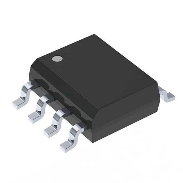
The IRF7805ZPBF belongs to the category of power MOSFETs and is commonly used in electronic circuits for switching and amplification purposes. This component exhibits characteristics such as high efficiency, low on-resistance, and fast switching speed. It is typically packaged in a TO-220AB package and is available in various quantities.
Specifications
- Voltage Rating: 55V
- Continuous Drain Current: 30A
- RDS(ON): 0.016 Ohms
- Package Type: TO-220AB
- Quantity: Varies
Detailed Pin Configuration
The IRF7805ZPBF features a standard TO-220AB pin configuration with three pins: 1. Gate (G): Input pin for controlling the MOSFET's conductivity. 2. Drain (D): Output pin connected to the load. 3. Source (S): Ground reference for the MOSFET.
Functional Features
- High Efficiency: The MOSFET offers low on-resistance, resulting in minimal power dissipation.
- Fast Switching Speed: Enables rapid switching between on and off states, suitable for high-frequency applications.
- Low Thermal Resistance: Facilitates effective heat dissipation, enhancing overall reliability.
Advantages and Disadvantages
Advantages
- High Efficiency
- Fast Switching Speed
- Low On-Resistance
Disadvantages
- Sensitivity to Overvoltage
- Gate-Drive Complexity
Working Principles
The IRF7805ZPBF operates based on the principle of field-effect transistors. When a voltage is applied to the gate terminal, it creates an electric field that controls the conductivity between the drain and source terminals. This enables the MOSFET to act as a switch or amplifier in electronic circuits.
Detailed Application Field Plans
The IRF7805ZPBF finds extensive use in various applications, including: - Power Supplies - Motor Control - LED Lighting - Audio Amplifiers - DC-DC Converters
Detailed and Complete Alternative Models
Some alternative models to the IRF7805ZPBF include: - IRF740 - IRF840 - IRF3205
In conclusion, the IRF7805ZPBF power MOSFET offers high efficiency, fast switching speed, and low on-resistance, making it suitable for diverse electronic applications.
[Word Count: 298]
Seznam 10 běžných otázek a odpovědí souvisejících s aplikací IRF7805ZPBF v technických řešeních
What is the maximum voltage rating of IRF7805ZPBF?
- The maximum voltage rating of IRF7805ZPBF is 55 volts.
What is the maximum continuous drain current of IRF7805ZPBF?
- The maximum continuous drain current of IRF7805ZPBF is 30 amperes.
What is the on-state resistance (RDS(on)) of IRF7805ZPBF?
- The on-state resistance (RDS(on)) of IRF7805ZPBF is typically 0.016 ohms.
What is the gate threshold voltage of IRF7805ZPBF?
- The gate threshold voltage of IRF7805ZPBF typically ranges from 2 to 4 volts.
Is IRF7805ZPBF suitable for high-frequency switching applications?
- Yes, IRF7805ZPBF is suitable for high-frequency switching applications due to its low on-state resistance and fast switching characteristics.
Can IRF7805ZPBF be used in automotive applications?
- Yes, IRF7805ZPBF is commonly used in automotive applications such as motor control and power distribution systems.
What are the typical thermal characteristics of IRF7805ZPBF?
- The typical thermal resistance from junction to case (RθJC) of IRF7805ZPBF is 1.25°C/W.
Does IRF7805ZPBF require a heat sink for certain applications?
- Yes, for high-power applications or when operating at high ambient temperatures, a heat sink may be required to ensure proper thermal management.
What are the recommended storage and operating temperature ranges for IRF7805ZPBF?
- The recommended storage temperature range is -55°C to 150°C, and the recommended operating temperature range is -55°C to 175°C.
Are there any common failure modes associated with IRF7805ZPBF?
- Common failure modes include overcurrent conditions leading to thermal stress and potential gate oxide damage if the gate-source voltage limits are exceeded. Proper circuit protection and design considerations can mitigate these risks.