

Viz Specifikace pro podrobnosti o produktu.
MAX6314US43D2+T
Basic Information Overview
- Category: Integrated Circuit (IC)
- Use: Voltage Monitor and Reset Circuit
- Characteristics:
- Monitors the voltage level of a power supply and generates a reset signal when the voltage falls below a specified threshold.
- Provides a reliable way to ensure proper system initialization and operation.
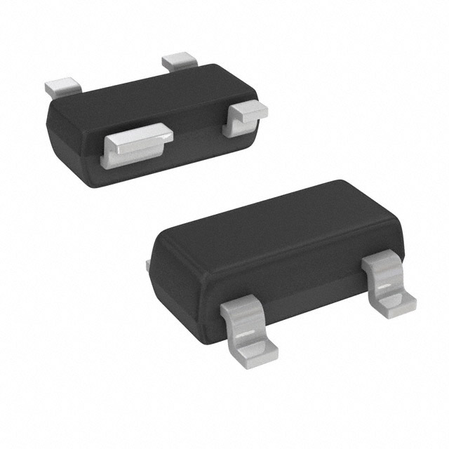
- Package: SOT-143
- Essence: Voltage monitoring and reset functionality in a compact package.
- Packaging/Quantity: Tape and Reel, 3000 units per reel.
Specifications
- Supply Voltage Range: 1.6V to 5.5V
- Threshold Voltage Options: 4.3V
- Reset Timeout Period: Adjustable or Fixed options available
- Operating Temperature Range: -40°C to +85°C
- Quiescent Current: 7µA (typical)
Detailed Pin Configuration
The MAX6314US43D2+T has four pins arranged as follows: 1. VCC: Power supply input pin. 2. GND: Ground reference pin. 3. RESET: Output pin for the reset signal. 4. MR: Active-low manual reset input pin.
Functional Features
- Voltage Monitoring: Monitors the supply voltage continuously.
- Reset Generation: Generates a reset signal when the voltage drops below the threshold.
- Manual Reset: Allows for an external manual reset option.
- Adjustable Timeout: Some variants allow adjustment of the reset timeout period.
- Low Power Consumption: Operates with low quiescent current, conserving power.
Advantages
- Compact Size: The SOT-143 package offers a small footprint, suitable for space-constrained applications.
- Wide Supply Voltage Range: Can operate with a wide range of supply voltages, enhancing versatility.
- Reliable Reset Functionality: Ensures proper system initialization and prevents erratic behavior due to insufficient power.
Disadvantages
- Fixed Threshold Voltage: The MAX6314US43D2+T has a fixed threshold voltage of 4.3V, limiting flexibility in certain applications.
- Limited Timeout Options: Some variants do not offer adjustable timeout periods, restricting customization.
Working Principles
The MAX6314US43D2+T operates by continuously monitoring the supply voltage using an internal voltage reference. When the voltage falls below the specified threshold (in this case, 4.3V), the circuit generates a reset signal on the RESET pin. This signal can be used to reset microcontrollers, digital logic circuits, or other system components. The MR pin allows for an external manual reset option, enabling system control. The low quiescent current ensures minimal power consumption during operation.
Detailed Application Field Plans
The MAX6314US43D2+T finds applications in various fields, including: 1. Embedded Systems: Provides reliable power-on reset functionality for microcontrollers and other embedded devices. 2. Industrial Automation: Ensures proper initialization of control systems and prevents erratic behavior due to voltage fluctuations. 3. Automotive Electronics: Monitors the vehicle's power supply and generates resets when necessary, enhancing system reliability. 4. Consumer Electronics: Used in devices such as smart home appliances, ensuring stable operation and preventing data loss during power interruptions.
Detailed and Complete Alternative Models
- MAX6315US43D2+T: Similar to MAX6314US43D2+T but with an adjustable reset timeout period.
- MAX6316US43D2+T: Offers a different threshold voltage option of 4.5V.
- MAX6317US43D2+T: Provides a fixed threshold voltage of 4.3V but with an active-high reset output.
(Note: These alternative models are just examples and not an exhaustive list.)
This entry provides an overview of the MAX6314US43D2+T, a voltage monitor and reset circuit IC. It includes information on its basic characteristics, specifications, pin configuration, functional features, advantages, disadvantages, working principles, application field plans, and alternative models.
Seznam 10 běžných otázek a odpovědí souvisejících s aplikací MAX6314US43D2+T v technických řešeních
Sure! Here are 10 common questions and answers related to the application of MAX6314US43D2+T in technical solutions:
Q: What is MAX6314US43D2+T? A: MAX6314US43D2+T is a voltage monitor and reset IC (integrated circuit) designed for use in various technical solutions.
Q: What is the purpose of MAX6314US43D2+T? A: The purpose of MAX6314US43D2+T is to monitor the power supply voltage and generate a reset signal when the voltage falls below a certain threshold.
Q: How does MAX6314US43D2+T work? A: MAX6314US43D2+T continuously monitors the input voltage and compares it with a reference voltage. If the input voltage drops below the reference voltage, it generates a reset signal.
Q: What is the operating voltage range of MAX6314US43D2+T? A: The operating voltage range of MAX6314US43D2+T is typically between 1.6V and 5.5V.
Q: Can MAX6314US43D2+T be used in battery-powered applications? A: Yes, MAX6314US43D2+T can be used in battery-powered applications as long as the operating voltage range is within the battery's voltage range.
Q: What is the typical reset timeout period of MAX6314US43D2+T? A: The typical reset timeout period of MAX6314US43D2+T is around 140ms.
Q: Can MAX6314US43D2+T be used in automotive applications? A: Yes, MAX6314US43D2+T is suitable for automotive applications as it can withstand the harsh operating conditions typically found in automotive environments.
Q: Does MAX6314US43D2+T have any built-in protection features? A: Yes, MAX6314US43D2+T has built-in overvoltage and undervoltage lockout protection to prevent damage to the IC and the connected circuitry.
Q: Can multiple MAX6314US43D2+T ICs be used in parallel for redundancy? A: Yes, multiple MAX6314US43D2+T ICs can be used in parallel to provide redundancy and improve system reliability.
Q: What package does MAX6314US43D2+T come in? A: MAX6314US43D2+T is available in a SOT-143 package, which is a small surface-mount package commonly used in electronic devices.
Please note that these answers are general and may vary depending on specific application requirements.