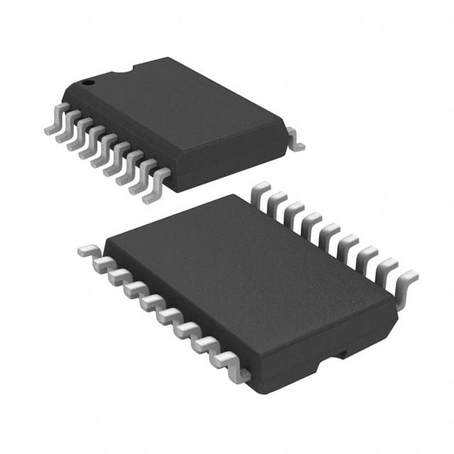
Viz Specifikace pro podrobnosti o produktu.

MCP2515-I/SO
Product Overview
- Category: Integrated Circuit (IC)
- Use: Controller Area Network (CAN) Bus Controller
- Characteristics:
- High-speed SPI interface
- Supports CAN V2.0B protocol
- Operates at 5V supply voltage
- Compatible with both 3.3V and 5V microcontrollers
- Package: SOIC (Small Outline Integrated Circuit)
- Essence: The MCP2515-I/SO is a widely used CAN bus controller IC that enables communication between microcontrollers and CAN networks.
- Packaging/Quantity: Available in tape and reel packaging, with a quantity of 2500 units per reel.
Specifications
- Supply Voltage: 4.5V to 5.5V
- Operating Temperature Range: -40°C to +85°C
- Maximum SPI Clock Frequency: 10 MHz
- Transmit/Receive Buffer Size: 3 TX and 2 RX buffers
- Bit Rate: Up to 1 Mbps
- Error Detection and Handling: Supports error detection and reporting mechanisms
Pin Configuration
The MCP2515-I/SO has a total of 20 pins, which are assigned as follows:
- VDD - Power Supply
- VSS - Ground
- OSC1 - Oscillator Input
- OSC2 - Oscillator Output
- CS - Chip Select
- SCK - Serial Clock
- SI - Serial Data Input
- SO - Serial Data Output
- INT - Interrupt Output
- RX0BF - Receive Buffer 0 Full
- RX1BF - Receive Buffer 1 Full
- TX0RTS - Transmit Buffer 0 Request-to-Send
- TX1RTS - Transmit Buffer 1 Request-to-Send
- TX2RTS - Transmit Buffer 2 Request-to-Send
- RX0 - Receive Pin 0
- RX1 - Receive Pin 1
- TX0 - Transmit Pin 0
- TX1 - Transmit Pin 1
- TX2 - Transmit Pin 2
- SDO - Serial Data Output (Alternate)
Functional Features
- High-speed SPI interface for easy integration with microcontrollers.
- Supports both standard (11-bit) and extended (29-bit) CAN identifiers.
- Three transmit buffers and two receive buffers for efficient message handling.
- Built-in error detection and reporting mechanisms ensure reliable communication.
- Configurable bit rates up to 1 Mbps for flexible network setups.
- Interrupt output pin for efficient event-driven processing.
Advantages and Disadvantages
Advantages: - Easy integration with microcontrollers through the SPI interface. - Supports both standard and extended CAN identifiers. - Multiple transmit and receive buffers enhance message handling efficiency. - Reliable communication ensured by error detection and reporting mechanisms. - Flexible bit rate configuration allows for various network setups.
Disadvantages: - Limited number of transmit and receive buffers may restrict complex communication scenarios. - Requires external oscillator components for clock generation.
Working Principles
The MCP2515-I/SO acts as a bridge between microcontrollers and Controller Area Network (CAN) networks. It communicates with the microcontroller using the high-speed Serial Peripheral Interface (SPI). The IC handles the transmission and reception of messages on the CAN bus, following the CAN V2.0B protocol.
When a microcontroller wants to send a message, it writes the data into one of the transmit buffers and requests transmission. The MCP2515-I/SO then takes care of sending the message onto the CAN bus. On the receiving side, the IC monitors the bus for incoming messages and stores them in the receive buffers. The microcontroller can then read these messages from the buffers.
The MCP2515-I/SO also performs error detection and reporting. It checks for errors like bit errors, frame errors, and acknowledgment errors, providing the microcontroller with information about the network's health.
Detailed Application Field Plans
The MCP2515-I/SO finds applications in various fields, including:
- Automotive: Used in automotive electronics for communication between different control units, such as engine management systems, body control modules, and instrument clusters.
- Industrial Automation: Enables communication between industrial devices and controllers, facilitating efficient control and monitoring of processes.
- Home Automation: Allows for seamless integration of smart home devices, enabling centralized control and automation.
- Medical Devices: Used in medical equipment to establish reliable communication between different components, ensuring accurate data exchange.
- Internet of Things (IoT): Facilitates connectivity and communication between IoT devices, enabling data sharing and remote control.
Alternative Models
- Microchip MCP25625: Similar CAN bus controller IC with enhanced features and improved performance.
- Texas Instruments SN65HVD230: CAN transceiver IC that complements the MCP2515-I/SO for complete CAN communication
Seznam 10 běžných otázek a odpovědí souvisejících s aplikací MCP2515-I/SO v technických řešeních
What is the maximum SPI clock frequency supported by MCP2515-I/SO?
- The maximum SPI clock frequency supported by MCP2515-I/SO is 10 MHz.Can MCP2515-I/SO be used with both 5V and 3.3V microcontrollers?
- Yes, MCP2515-I/SO can be used with both 5V and 3.3V microcontrollers.What is the operating voltage range of MCP2515-I/SO?
- The operating voltage range of MCP2515-I/SO is 2.7V to 5.5V.Does MCP2515-I/SO support CAN 2.0B protocol?
- Yes, MCP2515-I/SO supports CAN 2.0B protocol.What is the typical standby current consumption of MCP2515-I/SO?
- The typical standby current consumption of MCP2515-I/SO is 5 µA.Can MCP2515-I/SO be used in automotive applications?
- Yes, MCP2515-I/SO can be used in automotive applications.What is the maximum data rate supported by MCP2515-I/SO?
- The maximum data rate supported by MCP2515-I/SO is 1 Mbps.Is there a temperature range limitation for MCP2515-I/SO?
- MCP2515-I/SO has a temperature range of -40°C to 125°C.Can MCP2515-I/SO be used in industrial control systems?
- Yes, MCP2515-I/SO can be used in industrial control systems.What are the key features of MCP2515-I/SO?
- The key features of MCP2515-I/SO include integrated CAN controller, SPI interface, 2 receive buffers, 3 transmit buffers, etc.

