

Viz Specifikace pro podrobnosti o produktu.
Encyclopedia Entry: 74F569PC
Product Overview
Category
The 74F569PC belongs to the category of integrated circuits (ICs).
Use
This IC is commonly used in electronic devices for various applications, including data processing, signal amplification, and digital logic operations.
Characteristics
- The 74F569PC is a high-speed, 8-bit binary counter with parallel load.
- It operates on a wide voltage range, typically between 4.5V and 5.5V.
- This IC offers excellent noise immunity and low power consumption.
- It is designed to be compatible with other TTL (Transistor-Transistor Logic) devices.
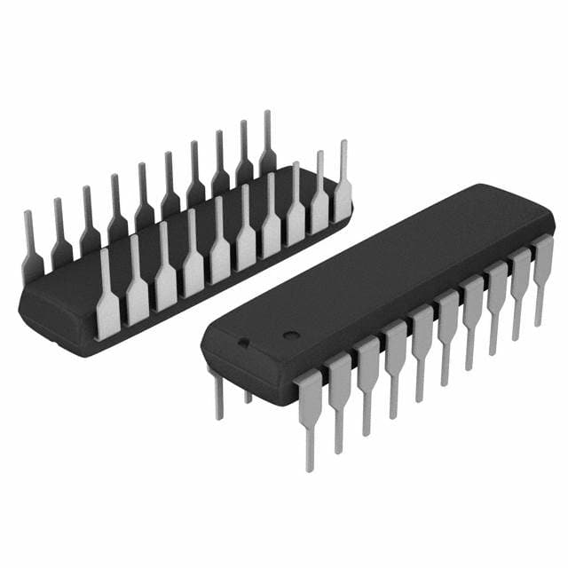
Package
The 74F569PC is available in a standard dual in-line package (DIP), which consists of 16 pins arranged in two rows.
Essence
The essence of the 74F569PC lies in its ability to count and store binary information, providing a crucial component for digital circuitry.
Packaging/Quantity
This IC is typically sold in reels or tubes containing multiple units. The exact quantity may vary depending on the supplier.
Specifications
- Supply Voltage: 4.5V - 5.5V
- Operating Temperature Range: -40°C to 85°C
- Maximum Clock Frequency: 50 MHz
- Input/Output Compatibility: TTL
Detailed Pin Configuration
The 74F569PC has 16 pins, each serving a specific function. Here is the detailed pin configuration:
- CLR (Clear): Resets the counter to its initial state.
- CLK (Clock): Provides the clock signal for counting.
- P0-P7 (Parallel Inputs): These pins allow the user to load data into the counter.
- Q0-Q7 (Parallel Outputs): These pins provide the output signals representing the current count value.
- GND (Ground): The reference ground for the IC.
- VCC (Power Supply): The positive power supply terminal.
Functional Features
- Parallel Load: The 74F569PC allows users to load data in parallel, enabling quick and efficient initialization of the counter.
- High-Speed Counting: With a maximum clock frequency of 50 MHz, this IC can perform rapid counting operations.
- Clear Function: The CLR pin enables the user to reset the counter to its initial state.
- TTL Compatibility: The 74F569PC is designed to be compatible with other TTL devices, ensuring seamless integration into existing digital circuits.
Advantages and Disadvantages
Advantages
- High-speed operation allows for efficient counting in time-critical applications.
- Excellent noise immunity ensures reliable performance even in noisy environments.
- Low power consumption contributes to energy-efficient designs.
- Parallel load capability enables quick initialization of the counter.
Disadvantages
- Limited voltage range may restrict its use in certain applications requiring higher or lower voltages.
- Availability may vary depending on the supplier and market demand.
Working Principles
The 74F569PC operates based on the principles of digital logic. It utilizes flip-flops and combinational logic to count and store binary information. The CLK signal triggers the counter to increment its value, while the CLR signal resets it to zero. The parallel load feature allows users to load specific values into the counter, providing flexibility in various applications.
Detailed Application Field Plans
The 74F569PC finds application in a wide range of electronic devices and systems, including: - Digital counters and timers - Frequency dividers - Data processing units - Signal generators - Industrial control systems
Detailed and Complete Alternative Models
While the 74F569PC offers specific features and characteristics, there are alternative models available that cater to different requirements. Some notable alternatives to consider include: - 74HC569: A CMOS-based binary counter with similar functionality but lower power consumption. - 74LS569: A low-power Schottky TTL counter with comparable performance characteristics.
These alternative models provide options for designers and engineers to choose the most suitable IC based on their specific needs.
Word count: 570 words
Seznam 10 běžných otázek a odpovědí souvisejících s aplikací 74F569PC v technických řešeních
Sure! Here are 10 common questions and answers related to the application of 74F569PC in technical solutions:
Q: What is the 74F569PC? A: The 74F569PC is a specific type of integrated circuit (IC) that is commonly used in electronic devices for various technical applications.
Q: What is the purpose of the 74F569PC? A: The 74F569PC is primarily used as an 8-bit binary counter with parallel load capability, making it useful for tasks such as counting, sequencing, and data manipulation.
Q: How does the 74F569PC work? A: The 74F569PC operates by receiving clock pulses and incrementing its internal counter based on those pulses. It can also be loaded with a specific value in parallel using its input pins.
Q: What voltage levels does the 74F569PC support? A: The 74F569PC typically supports a voltage range of 4.5V to 5.5V, making it compatible with most standard digital logic circuits.
Q: Can the 74F569PC be used in both synchronous and asynchronous applications? A: Yes, the 74F569PC can be used in both synchronous and asynchronous applications, depending on how it is connected and configured within the circuit.
Q: What are some common applications of the 74F569PC? A: Some common applications of the 74F569PC include frequency division, time delay generation, event sequencing, and digital data manipulation.
Q: How many output pins does the 74F569PC have? A: The 74F569PC has 8 output pins, each representing a different bit of the counter's value.
Q: Can the 74F569PC be cascaded to create larger counters? A: Yes, multiple 74F569PC ICs can be cascaded together to create larger counters with more bits, allowing for higher counting ranges.
Q: What is the maximum clock frequency that the 74F569PC can handle? A: The maximum clock frequency of the 74F569PC depends on various factors such as supply voltage and temperature, but it typically ranges from a few megahertz to tens of megahertz.
Q: Are there any specific precautions to consider when using the 74F569PC? A: It is important to ensure proper power supply decoupling and signal integrity when using the 74F569PC. Additionally, attention should be given to the maximum ratings and operating conditions specified in the datasheet to prevent damage or malfunctioning.
Please note that these answers are general and may vary depending on the specific implementation and requirements of your technical solution.