Viz Specifikace pro podrobnosti o produktu.

Encyclopedia Entry: 74F827SPC
Product Overview
Category
The 74F827SPC belongs to the category of integrated circuits (ICs).
Use
This IC is commonly used in digital electronic systems for various applications.
Characteristics
- The 74F827SPC is a high-speed, quad 10-bit buffer with 3-state outputs.
- It operates on a supply voltage range of 4.5V to 5.5V.
- This IC offers fast propagation delay times and low power consumption.
- It is designed to provide reliable performance in demanding digital circuitry.
Package
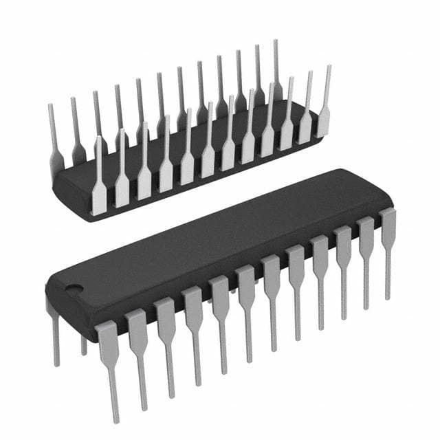
The 74F827SPC is available in a 20-pin small outline package (SOIC).
Essence
The essence of the 74F827SPC lies in its ability to buffer and amplify digital signals while maintaining signal integrity and minimizing delays.
Packaging/Quantity
This IC is typically sold in reels or tubes containing multiple units, with each reel/tube containing a specific quantity of 74F827SPC ICs.
Specifications
- Supply Voltage Range: 4.5V to 5.5V
- Operating Temperature Range: -40°C to +85°C
- Input Voltage High Level (VIH): 2.0V (min), 7.0V (max)
- Input Voltage Low Level (VIL): -1.0V (min), 0.8V (max)
- Output Voltage High Level (VOH): 2.4V (min), VCC (max)
- Output Voltage Low Level (VOL): 0.4V (max), 0.8V (max)
- Propagation Delay Time: 6ns (typical)
Detailed Pin Configuration
The 74F827SPC has a total of 20 pins, which are assigned specific functions. The pin configuration is as follows:
- Pin 1: Output Enable (OE) for Buffer 1
- Pin 2: Input A0 for Buffer 1
- Pin 3: Input B0 for Buffer 1
- Pin 4: Output Y0 for Buffer 1
- Pin 5: Ground (GND)
- Pin 6: Output Enable (OE) for Buffer 2
- Pin 7: Input A1 for Buffer 2
- Pin 8: Input B1 for Buffer 2
- Pin 9: Output Y1 for Buffer 2
- Pin 10: VCC (+5V)
- Pin 11: Output Enable (OE) for Buffer 3
- Pin 12: Input A2 for Buffer 3
- Pin 13: Input B2 for Buffer 3
- Pin 14: Output Y2 for Buffer 3
- Pin 15: Output Enable (OE) for Buffer 4
- Pin 16: Input A3 for Buffer 4
- Pin 17: Input B3 for Buffer 4
- Pin 18: Output Y3 for Buffer 4
- Pin 19: Not Connected (NC)
- Pin 20: VCC (+5V)
Functional Features
- The 74F827SPC provides four independent buffer circuits.
- Each buffer has separate output enable control (OE) and input data (A, B) pins.
- The outputs of the buffers are capable of driving high capacitive loads.
- The 3-state outputs allow multiple devices to be connected together without bus contention issues.
Advantages and Disadvantages
Advantages
- High-speed operation enables efficient signal buffering in digital systems.
- Low power consumption helps in reducing overall system energy requirements.
- 3-state outputs facilitate bus sharing and reduce conflicts in multi-device setups.
Disadvantages
- Limited voltage range (4.5V to 5.5V) may restrict compatibility with certain systems operating at different voltage levels.
- The package size (SOIC) might not be suitable for space-constrained applications.
Working Principles
The 74F827SPC operates by receiving digital input signals through the A and B pins of each buffer. These signals are then amplified and buffered internally. The output enable (OE) pin controls the state of the outputs, allowing them to be either active or in a high-impedance state. This IC utilizes advanced semiconductor technology to achieve high-speed operation and reliable performance.
Detailed Application Field Plans
The 74F827SPC finds applications in various digital electronic systems, including but not limited to: - Microprocessors and microcontrollers - Data communication systems - Memory interfaces - Industrial control systems - Test and measurement equipment
Detailed and Complete Alternative Models
Some alternative models that offer similar functionality to the
Seznam 10 běžných otázek a odpovědí souvisejících s aplikací 74F827SPC v technických řešeních
Sure! Here are 10 common questions and answers related to the application of 74F827SPC in technical solutions:
Q: What is the 74F827SPC? A: The 74F827SPC is a high-speed, low-power octal buffer/line driver with 3-state outputs.
Q: What is the maximum operating voltage for the 74F827SPC? A: The maximum operating voltage for the 74F827SPC is 5.5V.
Q: How many inputs and outputs does the 74F827SPC have? A: The 74F827SPC has 8 inputs and 8 outputs.
Q: What is the purpose of the 3-state outputs in the 74F827SPC? A: The 3-state outputs allow multiple devices to share a common bus without interfering with each other.
Q: What is the typical propagation delay of the 74F827SPC? A: The typical propagation delay of the 74F827SPC is 6 ns.
Q: Can the 74F827SPC be used in both TTL and CMOS logic systems? A: Yes, the 74F827SPC is compatible with both TTL and CMOS logic systems.
Q: What is the maximum output current that the 74F827SPC can drive? A: The 74F827SPC can drive up to 24 mA of output current.
Q: Is the 74F827SPC suitable for high-speed applications? A: Yes, the 74F827SPC is designed for high-speed operation and is suitable for applications requiring fast data transfer.
Q: Can the 74F827SPC be used in automotive applications? A: Yes, the 74F827SPC is qualified for automotive applications and meets the necessary standards.
Q: Are there any special considerations when designing with the 74F827SPC? A: It is important to ensure proper decoupling and power supply bypassing to minimize noise and ensure reliable operation.
Please note that these answers are general and may vary depending on specific datasheet specifications and application requirements.

