

Viz Specifikace pro podrobnosti o produktu.
FDPF10N50UT
Product Category
The FDPF10N50UT belongs to the category of power MOSFETs.
Basic Information Overview
- Use: The FDPF10N50UT is used as a power switch in various electronic circuits and applications.
- Characteristics: It is known for its high voltage capability, low on-state resistance, and fast switching speed.
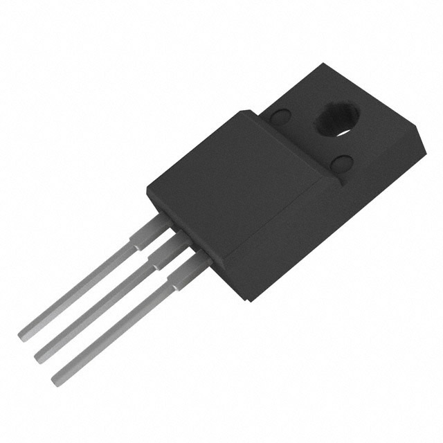
- Package: The FDPF10N50UT is typically available in a TO-220F package.
- Essence: This MOSFET is essential for controlling power flow in electronic devices.
- Packaging/Quantity: It is commonly packaged individually and sold in quantities suitable for production runs.
Specifications
- Voltage Rating: 500V
- Current Rating: 10A
- On-State Resistance: 0.65Ω
- Gate Threshold Voltage: 3V
- Operating Temperature Range: -55°C to 150°C
Detailed Pin Configuration
The FDPF10N50UT typically has three pins: 1. Gate (G): Used to control the switching of the MOSFET. 2. Drain (D): Connects to the load or circuit where power is being controlled. 3. Source (S): Connected to the ground or common reference point.
Functional Features
- High Voltage Capability: Can handle up to 500V, making it suitable for high-power applications.
- Low On-State Resistance: Enables efficient power transfer with minimal loss.
- Fast Switching Speed: Allows for rapid control of power flow in circuits.
Advantages and Disadvantages
Advantages: - High voltage capability - Low on-state resistance - Fast switching speed
Disadvantages: - May require additional circuitry for protection against voltage spikes and transients.
Working Principles
The FDPF10N50UT operates based on the principles of field-effect transistors, utilizing the voltage applied to the gate terminal to control the flow of current between the drain and source terminals.
Detailed Application Field Plans
The FDPF10N50UT is commonly used in the following applications: - Switching power supplies - Motor control circuits - Inverters and converters - Electronic ballasts
Detailed and Complete Alternative Models
Some alternative models to the FDPF10N50UT include: - IRF840 - STP16NF06 - FQP30N06L
This provides a comprehensive overview of the FDPF10N50UT, covering its category, basic information, specifications, pin configuration, functional features, advantages and disadvantages, working principles, application field plans, and alternative models.
Seznam 10 běžných otázek a odpovědí souvisejících s aplikací FDPF10N50UT v technických řešeních
What is FDPF10N50UT?
- FDPF10N50UT is a MOSFET (Metal-Oxide-Semiconductor Field-Effect Transistor) used for switching and amplifying electronic signals in various technical applications.
What are the key specifications of FDPF10N50UT?
- The FDPF10N50UT has a voltage rating of 500V, a current rating of 10A, and a low on-resistance, making it suitable for high-power applications.
How can FDPF10N50UT be used in power supply designs?
- FDPF10N50UT can be used in power supply designs to control the flow of power and regulate voltage levels due to its high voltage and current handling capabilities.
In what types of circuits can FDPF10N50UT be utilized?
- FDPF10N50UT can be utilized in various types of circuits such as motor control circuits, lighting systems, and audio amplifiers due to its high power-handling capabilities.
What are the thermal considerations when using FDPF10N50UT?
- Thermal considerations are important when using FDPF10N50UT due to its power dissipation characteristics. Proper heat sinking and thermal management should be implemented to ensure reliable operation.
Can FDPF10N50UT be used in automotive applications?
- Yes, FDPF10N50UT can be used in automotive applications such as electronic control units (ECUs), motor drives, and power distribution systems due to its high voltage and current ratings.
What are the typical operating conditions for FDPF10N50UT?
- The typical operating conditions for FDPF10N50UT include a maximum voltage of 500V, a maximum current of 10A, and a specified temperature range for reliable performance.
How does FDPF10N50UT compare to other MOSFETs in its class?
- FDPF10N50UT offers a balance of high voltage and current ratings with low on-resistance, making it suitable for a wide range of high-power applications compared to other MOSFETs in its class.
What protection features does FDPF10N50UT offer?
- FDPF10N50UT may offer protection features such as overcurrent protection, overvoltage protection, and thermal shutdown to safeguard the device and the circuit from potential damage.
Where can I find detailed application notes for using FDPF10N50UT in technical solutions?
- Detailed application notes for using FDPF10N50UT in technical solutions can be found in the product datasheet, manufacturer's application guides, and technical forums dedicated to electronic components and design.