

Viz Specifikace pro podrobnosti o produktu.
J111-D26Z Product Overview
1. Introduction
The J111-D26Z is a component belonging to the category of field-effect transistors (FETs). It is widely used in electronic circuits for various applications due to its unique characteristics and functional features.
2. Basic Information Overview
- Category: Field-Effect Transistor (FET)
- Use: Electronic circuitry, signal amplification, switching applications
- Characteristics: High input impedance, low noise, low power consumption
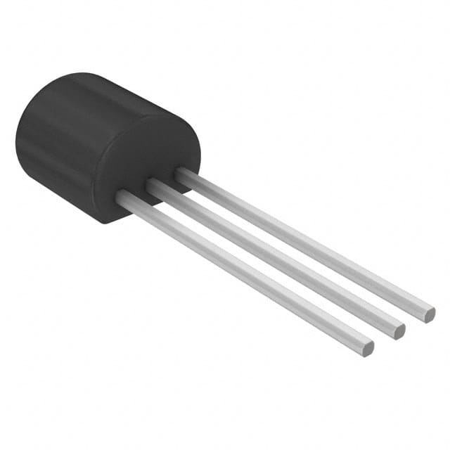
- Package: TO-92 package
- Essence: N-channel JFET (Junction Field-Effect Transistor)
- Packaging/Quantity: Typically available in reels or tubes containing multiple units
3. Specifications
- Maximum Drain-Source Voltage (Vds): 35V
- Maximum Gate-Source Voltage (Vgs): -35V
- Maximum Continuous Drain Current (Id): 50mA
- Maximum Power Dissipation (Pd): 350mW
- Operating Temperature Range: -55°C to 150°C
4. Detailed Pin Configuration
The J111-D26Z FET has three pins: Gate (G), Drain (D), and Source (S). The pin configuration is as follows: - Gate (G): Pin 1 - Drain (D): Pin 2 - Source (S): Pin 3
5. Functional Features
- High input impedance: Allows for minimal loading of preceding stages in a circuit.
- Low noise: Suitable for use in audio amplifier and sensor applications.
- Low power consumption: Ideal for battery-operated devices and low-power circuits.
6. Advantages and Disadvantages
- Advantages:
- Low noise performance
- High input impedance
- Versatile for various electronic applications
- Disadvantages:
- Limited maximum drain-source voltage
- Moderate maximum continuous drain current
7. Working Principles
The J111-D26Z operates based on the principles of field-effect transistors, where the flow of current between the drain and source terminals is controlled by the voltage applied to the gate terminal. This allows for efficient signal amplification and switching within electronic circuits.
8. Detailed Application Field Plans
The J111-D26Z finds application in various electronic circuits, including but not limited to: - Audio amplifiers - Sensor interfaces - Low-power switching circuits - Oscillator circuits
9. Detailed and Complete Alternative Models
- Alternative Models:
- J112-D26Z
- J113-D26Z
- 2N5457
- 2N5484
In conclusion, the J111-D26Z field-effect transistor offers high input impedance, low noise, and low power consumption, making it suitable for a wide range of electronic applications.
Word count: 398
Seznam 10 běžných otázek a odpovědí souvisejících s aplikací J111-D26Z v technických řešeních
Sure, here are 10 common questions and answers related to the application of J111-D26Z in technical solutions:
What is J111-D26Z?
- J111-D26Z is a specific model of electronic component, typically used as a junction field-effect transistor (JFET) in various technical applications.
What are the key specifications of J111-D26Z?
- The key specifications of J111-D26Z include its maximum drain-source voltage, gate-source voltage, and drain current, as well as its transconductance and input capacitance.
In what types of technical solutions is J111-D26Z commonly used?
- J111-D26Z is commonly used in audio amplifiers, analog switches, signal processing circuits, and other applications where low noise and high input impedance are important.
How does J111-D26Z compare to other similar components in terms of performance?
- J111-D26Z is known for its low noise and high input impedance, making it suitable for applications where these characteristics are critical.
What are the typical operating conditions for J111-D26Z?
- The typical operating conditions for J111-D26Z include a specified range of voltages and currents, as well as temperature limits for proper functionality.
Can J111-D26Z be used in high-frequency applications?
- While J111-D26Z is not specifically designed for high-frequency applications, it can still be used in certain low to moderate frequency circuits.
Are there any special considerations for using J111-D26Z in circuit design?
- Designers should consider the biasing requirements, input impedance matching, and potential for thermal effects when incorporating J111-D26Z into their circuits.
What are the typical failure modes of J111-D26Z?
- Common failure modes for J111-D26Z may include overvoltage stress, excessive power dissipation, and electrostatic discharge (ESD) events.
Can J111-D26Z be replaced with a different component in a circuit?
- It's important to carefully evaluate the specifications and characteristics of alternative components before substituting them for J111-D26Z in a circuit.
Where can I find detailed application notes and reference designs for using J111-D26Z in technical solutions?
- Detailed application notes and reference designs for J111-D26Z can often be found in the manufacturer's datasheets, application guides, or technical support resources.
I hope these questions and answers provide helpful information about the application of J111-D26Z in technical solutions! If you have any further questions, feel free to ask.