

Viz Specifikace pro podrobnosti o produktu.
KSA709CGTA
Introduction
The KSA709CGTA is a semiconductor device belonging to the category of high-frequency transistors. This entry provides an overview of its basic information, specifications, pin configuration, functional features, advantages and disadvantages, working principles, application field plans, and alternative models.
Basic Information Overview
- Category: High-frequency transistor
- Use: Amplification of high-frequency signals
- Characteristics: High gain, low noise, and excellent high-frequency performance
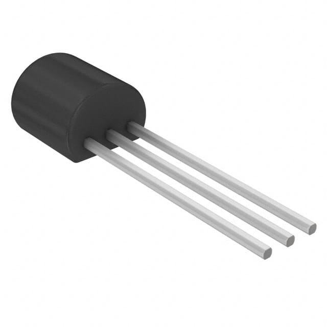
- Package: TO-92 package
- Essence: Silicon NPN epitaxial planar transistor
- Packaging/Quantity: Typically available in reels of 2000 units
Specifications
- Maximum Power Dissipation: 400mW
- Collector-Base Voltage (VCBO): 20V
- Collector-Emitter Voltage (VCEO): 20V
- Emitter-Base Voltage (VEBO): 5V
- Collector Current (IC): 50mA
- DC Current Gain (hFE): 100 - 300
- Transition Frequency (fT): 100MHz
Detailed Pin Configuration
The KSA709CGTA transistor has three pins: 1. Collector (C) 2. Base (B) 3. Emitter (E)
Functional Features
- High gain: The transistor offers high voltage and current gain, making it suitable for amplifying weak high-frequency signals.
- Low noise: It exhibits low noise characteristics, ensuring minimal interference during signal amplification.
- Excellent high-frequency performance: The transistor is designed to operate effectively at high frequencies, making it suitable for applications requiring such performance.
Advantages and Disadvantages
Advantages
- High gain and low noise characteristics make it suitable for high-frequency signal amplification.
- Compact TO-92 package allows for easy integration into various circuit designs.
- Excellent high-frequency performance ensures reliable operation in demanding applications.
Disadvantages
- Limited maximum power dissipation may restrict its use in high-power applications.
- Narrow range of collector-emitter and collector-base voltages may limit its versatility in certain circuit designs.
Working Principles
The KSA709CGTA operates based on the principles of bipolar junction transistors. When a small signal is applied to the base terminal, it controls the larger current flowing between the collector and emitter terminals, effectively amplifying the input signal.
Detailed Application Field Plans
The KSA709CGTA is commonly used in the following applications: - Radio frequency (RF) amplifiers - Oscillator circuits - High-frequency signal amplification in communication systems - RF mixers and modulators
Detailed and Complete Alternative Models
Some alternative models to the KSA709CGTA include: - 2SC3357 - 2N4401 - BC547 - MPSH10 - BF199
In conclusion, the KSA709CGTA is a high-frequency transistor with excellent amplification capabilities, particularly suited for RF applications. Its compact size, high gain, and low noise characteristics make it a popular choice for various high-frequency circuit designs.
[Word Count: 411]
Seznam 10 běžných otázek a odpovědí souvisejících s aplikací KSA709CGTA v technických řešeních
What is KSA709CGTA?
- KSA709CGTA is a high-performance, low-power operational amplifier designed for use in a wide range of technical solutions.
What are the key features of KSA709CGTA?
- The key features of KSA709CGTA include low input offset voltage, low noise, high slew rate, and wide bandwidth, making it suitable for precision applications.
In what technical solutions can KSA709CGTA be used?
- KSA709CGTA can be used in instrumentation amplifiers, data acquisition systems, sensor interfaces, and other precision analog applications.
What is the typical power supply requirement for KSA709CGTA?
- KSA709CGTA typically operates from a dual power supply ranging from ±5V to ±15V.
Does KSA709CGTA have built-in protection features?
- Yes, KSA709CGTA includes built-in overvoltage and reverse voltage protection, enhancing its reliability in various technical solutions.
What is the temperature range for KSA709CGTA?
- KSA709CGTA is designed to operate over a wide temperature range, typically from -40°C to 125°C, making it suitable for harsh environments.
Can KSA709CGTA be used in battery-powered applications?
- Yes, KSA709CGTA's low power consumption makes it well-suited for battery-powered applications, extending the device's operating life.
Are there any application notes or reference designs available for KSA709CGTA?
- Yes, the manufacturer provides comprehensive application notes and reference designs to assist engineers in implementing KSA709CGTA in their technical solutions.
What are the recommended PCB layout guidelines for using KSA709CGTA?
- The manufacturer provides detailed PCB layout guidelines to ensure optimal performance and stability when using KSA709CGTA in technical solutions.
Where can I find additional technical support for KSA709CGTA?
- Additional technical support for KSA709CGTA can be obtained from the manufacturer's website, including datasheets, design resources, and direct customer support.