

Viz Specifikace pro podrobnosti o produktu.
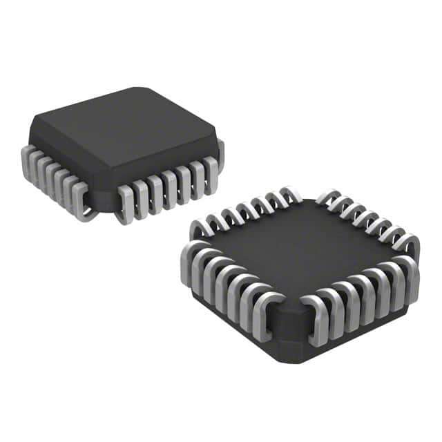
MC100E141FN
Product Overview
- Category: Integrated Circuit (IC)
- Use: Logic Gate
- Characteristics: High-speed, ECL (Emitter-Coupled Logic) compatible, differential input
- Package: 28-pin PLCC (Plastic Leaded Chip Carrier)
- Essence: This IC is designed to perform logic functions in high-speed digital circuits.
- Packaging/Quantity: Available in tubes of 25 units or reels of 1,000 units.
Specifications
- Supply Voltage: +4.2V to +5.7V
- Input Voltage: -2.0V to +7.0V
- Output Voltage: -2.0V to +5.7V
- Operating Temperature: -40°C to +85°C
- Propagation Delay: 1.6 ns (typical)
- Output Current: ±50 mA (maximum)
Pin Configuration
The MC100E141FN has a total of 28 pins. The pin configuration is as follows:
- VEE
- Q0
- Q1
- Q2
- Q3
- GND
- D0
- D1
- D2
- D3
- VCC
- Q4
- Q5
- Q6
- Q7
- GND
- D4
- D5
- D6
- D7
- VBB
- Q8
- Q9
- Q10
- Q11
- GND
- D8
- D9
Functional Features
- High-speed operation: The MC100E141FN is capable of operating at very high speeds, making it suitable for use in applications that require fast signal processing.
- ECL compatibility: This IC is designed to be compatible with Emitter-Coupled Logic (ECL) circuits, allowing for seamless integration into existing ECL-based systems.
- Differential input: The differential input configuration of the MC100E141FN allows for improved noise immunity and better signal integrity.
Advantages and Disadvantages
Advantages: - High-speed operation enables efficient signal processing. - ECL compatibility ensures easy integration into existing ECL-based systems. - Differential input provides improved noise immunity.
Disadvantages: - Limited supply voltage range may restrict its use in certain applications. - Higher power consumption compared to some other logic gate technologies.
Working Principles
The MC100E141FN operates based on the principles of Emitter-Coupled Logic. It utilizes differential inputs to compare and process digital signals. The internal circuitry performs logical operations on the input signals and generates corresponding output signals. The high-speed operation of this IC is achieved through optimized transistor configurations and circuit design.
Detailed Application Field Plans
The MC100E141FN can be used in various applications that require high-speed logic functions. Some potential application fields include:
- Telecommunications: The IC can be used in high-speed data transmission systems, such as fiber optic networks, where quick signal processing is crucial.
- Computer Networking: It can be employed in routers, switches, and other networking equipment to handle fast data routing and switching operations.
- Industrial Automation: The IC can be utilized in control systems and programmable logic controllers (PLCs) to perform rapid logic operations for process control and automation.
- Test and Measurement Equipment: It can be integrated into test instruments, such as oscilloscopes and logic analyzers, to enable high-speed signal analysis and measurement.
Alternative Models
Here are some alternative models that offer similar functionality to the MC100E141FN:
- MC10ELT21: ECL-compatible differential input AND/NAND gate.
- MC100EP16: ECL-compatible differential input XOR/XNOR gate.
- MC100LVEL11: ECL-compatible differential input D-type flip-flop.
These alternative models can be considered based on specific application requirements and compatibility with existing systems.
Word count: 446 words
Seznam 10 běžných otázek a odpovědí souvisejících s aplikací MC100E141FN v technických řešeních
Sure! Here are 10 common questions and answers related to the application of MC100E141FN in technical solutions:
Q: What is MC100E141FN? A: MC100E141FN is a high-speed, low-power ECL (Emitter-Coupled Logic) differential receiver designed for use in various communication and data transmission systems.
Q: What are the key features of MC100E141FN? A: Some key features of MC100E141FN include differential inputs, wide operating voltage range, high-speed operation up to 1.3 GHz, and low power consumption.
Q: What is the typical application of MC100E141FN? A: MC100E141FN is commonly used in applications such as clock distribution, data synchronization, phase-locked loops (PLLs), and high-speed data transmission systems.
Q: What is the operating voltage range of MC100E141FN? A: The operating voltage range of MC100E141FN is typically between -4.2V and -5.7V.
Q: Can MC100E141FN be used with single-ended signals? A: No, MC100E141FN is designed for differential signaling and cannot be directly used with single-ended signals. However, it can be paired with a differential-to-single-ended converter if needed.
Q: What is the maximum data rate supported by MC100E141FN? A: MC100E141FN supports high-speed operation up to 1.3 GHz, making it suitable for applications requiring fast data transmission.
Q: Does MC100E141FN have built-in termination resistors? A: No, MC100E141FN does not have built-in termination resistors. External termination resistors should be used to match the characteristic impedance of the transmission line.
Q: What is the power supply requirement for MC100E141FN? A: MC100E141FN requires a dual power supply with VCC = -5.2V and VEE = -4.5V for proper operation.
Q: Can MC100E141FN tolerate overvoltage or ESD events? A: MC100E141FN does not have built-in protection against overvoltage or electrostatic discharge (ESD). Additional external protection measures should be implemented to safeguard the device.
Q: Are there any recommended layout guidelines for using MC100E141FN? A: Yes, it is recommended to follow the layout guidelines provided in the datasheet, including proper grounding, decoupling capacitors, and minimizing trace lengths to reduce noise and ensure signal integrity.
Please note that these answers are general and may vary depending on specific application requirements. It is always advisable to refer to the manufacturer's datasheet and application notes for detailed information.