

Viz Specifikace pro podrobnosti o produktu.
MC74HC595ADTR2
Product Overview
- Category: Integrated Circuit
- Use: Shift Register
- Characteristics: High-Speed, Serial-In Parallel-Out (SIPO), 8-bit
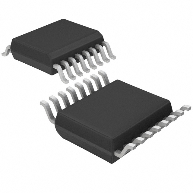
- Package: TSSOP-16
- Essence: Serial to Parallel Data Conversion
- Packaging/Quantity: Tape and Reel, 2500 units per reel
Specifications
- Supply Voltage Range: 2V to 6V
- Input Voltage Range: 0V to VCC
- Output Voltage Range: 0V to VCC
- Operating Temperature Range: -40°C to +85°C
- Maximum Clock Frequency: 25 MHz
- Maximum Output Current: 6 mA
- Maximum Power Dissipation: 500 mW
Pin Configuration
The MC74HC595ADTR2 has a total of 16 pins. The pin configuration is as follows:
- QH' (Output)
- QH (Output)
- DS (Serial Data Input)
- OE (Output Enable)
- ST_CP (Storage Register Clock Input)
- SH_CP (Shift Register Clock Input)
- MR (Master Reset)
- GND (Ground)
- QG (Output)
- QF (Output)
- QE (Output)
- QD (Output)
- QC (Output)
- QB (Output)
- QA (Output)
- VCC (Supply Voltage)
Functional Features
- Serial-in parallel-out shift register functionality
- High-speed data transfer with a maximum clock frequency of 25 MHz
- Output enable control for easy data storage and retrieval
- Master reset function for clearing the register
- Wide supply voltage range allows flexibility in different applications
Advantages and Disadvantages
Advantages: - High-speed operation enables efficient data transfer - Compact TSSOP-16 package saves board space - Wide supply voltage range allows compatibility with various systems
Disadvantages: - Limited output current may restrict certain applications - Lack of built-in protection features for overvoltage or overcurrent conditions
Working Principles
The MC74HC595ADTR2 is a serial-in parallel-out shift register. It accepts data serially through the DS pin and shifts it into the internal shift register on each rising edge of the SHCP (Shift Register Clock) input. The STCP (Storage Register Clock) input latches the data from the shift register into the storage register, making it available at the outputs. The OE (Output Enable) pin controls the output state, allowing the user to enable or disable the outputs as needed. The MR (Master Reset) pin resets the shift register and storage register to their initial states.
Detailed Application Field Plans
The MC74HC595ADTR2 is commonly used in various applications, including:
- LED Matrix Displays: The shift register functionality allows efficient control of multiple LEDs in a matrix configuration.
- Seven-Segment Displays: The outputs can be connected to the segments of a seven-segment display, enabling numeric or alphanumeric representation.
- Data Storage and Retrieval: The storage register feature makes it suitable for applications requiring temporary data storage, such as data logging or buffering.
- Serial Communication Interfaces: The shift register can be used to convert serial data to parallel format for interfacing with other devices.
Detailed and Complete Alternative Models
- SN74HC595N: Similar shift register IC with DIP-16 package.
- CD4094BE: 8-bit shift register and latch IC with DIP-16 package.
- 74HCT595: High-speed CMOS shift register IC with similar functionality.
These alternative models offer similar functionality and can be used as replacements for the MC74HC595ADTR2 in various applications.
Word count: 436 words
Seznam 10 běžných otázek a odpovědí souvisejících s aplikací MC74HC595ADTR2 v technických řešeních
Sure! Here are 10 common questions and answers related to the application of MC74HC595ADTR2:
Q: What is MC74HC595ADTR2? A: MC74HC595ADTR2 is a shift register with output latches, commonly used in digital electronics for expanding the number of outputs from a microcontroller.
Q: How many outputs does MC74HC595ADTR2 have? A: MC74HC595ADTR2 has 8 outputs that can be individually controlled.
Q: Can MC74HC595ADTR2 be used to drive LEDs? A: Yes, MC74HC595ADTR2 is often used to drive LEDs as it can provide sufficient current to light up multiple LEDs.
Q: How do I connect MC74HC595ADTR2 to a microcontroller? A: MC74HC595ADTR2 is connected to a microcontroller using three control pins (SER, SRCLK, RCLK) and one data pin (QH'). The control pins are used for shifting data into the shift register, while the data pin outputs the shifted data.
Q: Can MC74HC595ADTR2 be cascaded to increase the number of outputs? A: Yes, multiple MC74HC595ADTR2 chips can be cascaded together to expand the number of outputs. This is achieved by connecting the QH' output of one chip to the SER input of the next chip.
Q: What is the maximum clock frequency supported by MC74HC595ADTR2? A: MC74HC595ADTR2 can operate at a maximum clock frequency of 25 MHz.
Q: Can MC74HC595ADTR2 be used with both 3.3V and 5V microcontrollers? A: Yes, MC74HC595ADTR2 is compatible with both 3.3V and 5V microcontrollers as it has a wide operating voltage range (2V to 6V).
Q: How much current can each output of MC74HC595ADTR2 sink/source? A: Each output of MC74HC595ADTR2 can sink/source up to 25mA of current.
Q: Can MC74HC595ADTR2 be used for driving other types of loads besides LEDs? A: Yes, MC74HC595ADTR2 can be used to drive various types of loads such as relays, motors, and transistors, provided that the load current is within the specified limits.
Q: Are there any limitations or considerations when using MC74HC595ADTR2? A: One limitation is that MC74HC595ADTR2 is not designed to handle high voltages, so it should not be used directly with high voltage devices. Additionally, care should be taken to ensure that the total current drawn from all outputs does not exceed the maximum limit of the chip.