

Viz Specifikace pro podrobnosti o produktu.
MC74LVX138DTR2G
Product Overview
- Category: Integrated Circuit
- Use: Decoder/Demultiplexer
- Characteristics: Low-voltage, high-speed, 3-to-8 line decoder/demultiplexer
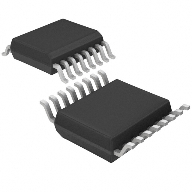
- Package: TSSOP-16
- Essence: Decodes a three-bit binary input to one of eight outputs
- Packaging/Quantity: Tape and Reel, 2500 units per reel
Specifications
- Supply Voltage Range: 1.65V to 5.5V
- High-Level Input Voltage: 2.0V to VCC + 0.3V
- Low-Level Input Voltage: -0.3V to 0.8V
- High-Level Output Current: -24mA
- Low-Level Output Current: 24mA
- Maximum Operating Frequency: 200MHz
Detailed Pin Configuration
The MC74LVX138DTR2G has a total of 16 pins:
- GND (Ground)
- A0 (Address Input Bit 0)
- A1 (Address Input Bit 1)
- A2 (Address Input Bit 2)
- E1 (Enable Input 1)
- Y0 (Output 0)
- Y1 (Output 1)
- Y2 (Output 2)
- Y3 (Output 3)
- Y4 (Output 4)
- Y5 (Output 5)
- Y6 (Output 6)
- Y7 (Output 7)
- E2 (Enable Input 2)
- VCC (Positive Power Supply)
- GND (Ground)
Functional Features
The MC74LVX138DTR2G is a decoder/demultiplexer integrated circuit that takes a three-bit binary input and decodes it to one of eight outputs. It operates at low voltage and high speed, making it suitable for various applications.
Advantages and Disadvantages
Advantages: - Low-voltage operation allows for compatibility with a wide range of systems - High-speed decoding enables quick response times - Compact TSSOP-16 package saves board space - Wide supply voltage range enhances flexibility in design
Disadvantages: - Limited to 3-to-8 line decoding, not suitable for larger-scale applications - May require additional components for certain configurations
Working Principles
The MC74LVX138DTR2G works by accepting three address input bits (A0, A1, and A2) and two enable inputs (E1 and E2). Based on the combination of these inputs, one of the eight outputs (Y0 to Y7) is activated. The decoder/demultiplexer operates using CMOS technology, allowing for low-voltage operation and high-speed performance.
Detailed Application Field Plans
The MC74LVX138DTR2G can be used in various applications, including but not limited to:
- Address decoding in microcontrollers and microprocessors
- Memory selection in digital systems
- Data routing in communication systems
- Signal demultiplexing in multimedia devices
- Control signal generation in industrial automation
Detailed and Complete Alternative Models
- SN74LV138A: Similar 3-to-8 line decoder/demultiplexer from Texas Instruments
- CD74HC138: 3-to-8 line decoder/demultiplexer with higher operating frequency from Texas Instruments
- 74HCT138: 3-to-8 line decoder/demultiplexer with TTL-compatible inputs from NXP Semiconductors
These alternative models offer similar functionality and can be considered as substitutes for the MC74LVX138DTR2G.
In conclusion, the MC74LVX138DTR2G is a low-voltage, high-speed decoder/demultiplexer integrated circuit. It provides eight outputs based on a three-bit binary input and finds applications in various fields. Its compact package and wide supply voltage range make it a versatile choice for designers.
Seznam 10 běžných otázek a odpovědí souvisejících s aplikací MC74LVX138DTR2G v technických řešeních
Sure! Here are 10 common questions and answers related to the application of MC74LVX138DTR2G in technical solutions:
Q: What is MC74LVX138DTR2G? A: MC74LVX138DTR2G is a 3-to-8 line decoder/demultiplexer integrated circuit (IC) commonly used in digital electronics.
Q: What is the purpose of MC74LVX138DTR2G? A: The purpose of MC74LVX138DTR2G is to decode binary information from three input lines into eight output lines, enabling selection of one out of eight possible outputs.
Q: What voltage levels does MC74LVX138DTR2G support? A: MC74LVX138DTR2G supports voltage levels ranging from 2.0V to 5.5V.
Q: How many inputs does MC74LVX138DTR2G have? A: MC74LVX138DTR2G has three input lines (A0, A1, and A2) for decoding purposes.
Q: How many output lines does MC74LVX138DTR2G have? A: MC74LVX138DTR2G has eight output lines (Y0-Y7) that can be selected based on the input combination.
Q: Can MC74LVX138DTR2G be cascaded to increase the number of outputs? A: Yes, multiple MC74LVX138DTR2G ICs can be cascaded together to increase the number of outputs.
Q: What is the maximum current that MC74LVX138DTR2G can source or sink? A: MC74LVX138DTR2G can source or sink up to 24mA of current per output.
Q: What is the typical propagation delay of MC74LVX138DTR2G? A: The typical propagation delay of MC74LVX138DTR2G is around 5ns.
Q: Can MC74LVX138DTR2G be used in both CMOS and TTL logic systems? A: Yes, MC74LVX138DTR2G is compatible with both CMOS and TTL logic systems.
Q: What are some common applications of MC74LVX138DTR2G? A: MC74LVX138DTR2G is commonly used in address decoding, memory selection, data routing, and general-purpose digital logic applications.
Please note that these answers are general and may vary depending on specific use cases and datasheet specifications.