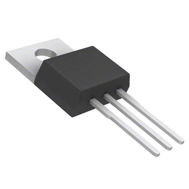
Viz Specifikace pro podrobnosti o produktu.

TIP121 Transistor: Encyclopedia Entry
Introduction
The TIP121 is a versatile and widely used transistor that belongs to the category of power transistors. This entry provides an overview of the TIP121, including its basic information, specifications, pin configuration, functional features, advantages and disadvantages, working principles, application field plans, and alternative models.
Basic Information Overview
- Category: Power Transistor
- Use: Amplification and Switching Applications
- Characteristics: High Voltage and Current Capability, Low Saturation Voltage
- Package: TO-220
- Essence: Power Amplification and Switching
- Packaging/Quantity: Typically available in packs of 10 or 25 units
Specifications
- Collector-Emitter Voltage (VCEO): 60V
- Collector-Base Voltage (VCBO): 60V
- Emitter-Base Voltage (VEBO): 5V
- Collector Current (IC): 5A
- Power Dissipation (PD): 65W
- Gain (hFE): 1000 (min) at IC = 3A, VCE = 4V
Detailed Pin Configuration
The TIP121 transistor has a standard TO-220 package with three pins: 1. Base (B) 2. Collector (C) 3. Emitter (E)
Functional Features
- High Voltage and Current Capability
- Low Saturation Voltage
- Fast Switching Speed
- Complementary NPN Type (TIP120)
Advantages and Disadvantages
Advantages
- Suitable for high-power applications
- Low saturation voltage reduces power dissipation
- Fast switching speed enables efficient operation
Disadvantages
- May require heat sinking in high-power applications
- Limited frequency response compared to small-signal transistors
Working Principles
The TIP121 operates as a bipolar junction transistor (BJT), where the flow of current between the collector and emitter is controlled by the current flowing into the base terminal. It amplifies or switches electronic signals based on the input current applied to the base.
Detailed Application Field Plans
The TIP121 transistor finds extensive use in various applications, including: - Power Amplification in Audio Systems - Motor Control in Robotics and Automation - Switching High-Power Loads in Industrial Equipment - Voltage Regulation Circuits
Detailed and Complete Alternative Models
Several alternative models to the TIP121 include: - TIP122: Higher Collector Current (8A) - TIP125: Higher Collector-Emitter Voltage (80V) - TIP126: Complementary PNP Type
In conclusion, the TIP121 transistor is a crucial component in power amplification and switching applications, offering high voltage and current capabilities, low saturation voltage, and fast switching speed. Its versatility and reliability make it a popular choice in various electronic circuits and systems.
Word Count: 411
Seznam 10 běžných otázek a odpovědí souvisejících s aplikací TIP121 v technických řešeních
What is TIP121?
- TIP121 is a general-purpose NPN Darlington transistor commonly used in electronic circuits for amplification and switching applications.
What are the typical applications of TIP121?
- TIP121 is often used in applications such as motor control, relay drivers, lamp drivers, LED displays, and other medium- to high-power switching circuits.
What is the pin configuration of TIP121?
- The TIP121 transistor has three pins: the emitter (E), base (B), and collector (C).
What is the maximum collector current rating of TIP121?
- The maximum collector current rating of TIP121 is typically around 5A.
How do I connect TIP121 in a circuit for switching applications?
- To use TIP121 for switching, you would typically connect the load between the collector and the positive power supply, with the emitter connected to ground. The base is then driven by a suitable input signal through a current-limiting resistor.
Can TIP121 be used for PWM (Pulse Width Modulation) applications?
- Yes, TIP121 can be used in PWM applications to control the speed of motors or the brightness of LEDs.
What are the typical voltage ratings for TIP121?
- TIP121 typically has a maximum collector-emitter voltage (Vce) rating of around 60V.
How do I calculate the base current required for TIP121 in a specific application?
- The base current required for TIP121 can be calculated using the formula Ib = Ic / hfe, where Ib is the base current, Ic is the collector current, and hfe is the current gain of the transistor.
What are some common alternatives to TIP121?
- Some common alternatives to TIP121 include TIP120, TIP122, and TIP125, which have similar characteristics and can be used in similar applications.
Are there any important considerations when using TIP121 in high-power applications?
- In high-power applications, it's important to consider heat dissipation and ensure that the TIP121 is mounted on a suitable heatsink to prevent overheating.

