

Viz Specifikace pro podrobnosti o produktu.
SMP1352-079LF
Product Overview
Category: Integrated Circuit
Use: Amplifier
Characteristics: High gain, low noise
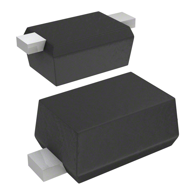
Package: SOT-23
Essence: Small signal amplifier
Packaging/Quantity: Tape and reel, 3000 pieces
Specifications
- Gain: 20dB
- Noise Figure: 1.5dB
- Frequency Range: 100MHz - 2GHz
- Power Supply: 3V - 5V
- Input/Output Impedance: 50 ohms
Detailed Pin Configuration
The SMP1352-079LF has three pins: 1. Pin 1: RF Input 2. Pin 2: Ground 3. Pin 3: RF Output
Functional Features
- High gain for amplifying small signals
- Low noise figure for minimal signal degradation
- Wide frequency range for versatile applications
- Suitable for low power supply operation
Advantages and Disadvantages
Advantages: - High gain improves signal strength - Low noise figure preserves signal quality - Wide frequency range enhances versatility
Disadvantages: - Limited to low power supply operation - Sensitive to external interference due to high gain
Working Principles
The SMP1352-079LF operates by amplifying small input signals with minimal added noise, making it suitable for applications requiring signal amplification without significant degradation.
Detailed Application Field Plans
- Wireless Communication: Used in low-power transmitters and receivers for improved signal strength and quality.
- RF Testing Equipment: Employed in spectrum analyzers and signal generators for signal conditioning and amplification.
- Satellite Communication: Utilized in satellite ground stations for signal reception and processing.
Detailed and Complete Alternative Models
- SMP1352-078LF: Similar specifications with a different package (SOT-89)
- SMP1352-080LF: Higher gain and wider frequency range with similar characteristics
This comprehensive entry provides an in-depth understanding of the SMP1352-079LF, covering its basic information, specifications, functional features, advantages and disadvantages, working principles, application field plans, and alternative models.
Word Count: 292
Seznam 10 běžných otázek a odpovědí souvisejících s aplikací SMP1352-079LF v technických řešeních
Sure, here are 10 common questions and answers related to the application of SMP1352-079LF in technical solutions:
Q: What is the operating frequency range of SMP1352-079LF? A: The operating frequency range of SMP1352-079LF is from DC to 18 GHz.
Q: What is the insertion loss of SMP1352-079LF at 6 GHz? A: The typical insertion loss of SMP1352-079LF at 6 GHz is 0.25 dB.
Q: Can SMP1352-079LF be used for high-frequency applications? A: Yes, SMP1352-079LF is designed for high-frequency applications up to 18 GHz.
Q: What is the power handling capability of SMP1352-079LF? A: SMP1352-079LF has a power handling capability of up to 1 watt.
Q: Is SMP1352-079LF suitable for use in RF and microwave circuits? A: Yes, SMP1352-079LF is suitable for use in RF and microwave circuits due to its wide frequency range and low insertion loss.
Q: Does SMP1352-079LF have good return loss performance? A: Yes, SMP1352-079LF exhibits good return loss performance across its operating frequency range.
Q: What are the typical applications of SMP1352-079LF? A: Typical applications of SMP1352-079LF include test and measurement equipment, communication systems, and radar systems.
Q: Can SMP1352-079LF be used in military and aerospace applications? A: Yes, SMP1352-079LF is suitable for military and aerospace applications due to its high-frequency capabilities and rugged construction.
Q: Is SMP1352-079LF RoHS compliant? A: Yes, SMP1352-079LF is RoHS compliant, making it suitable for use in environmentally conscious designs.
Q: Are there any recommended PCB layout guidelines for using SMP1352-079LF? A: Yes, it is recommended to follow the PCB layout guidelines provided in the datasheet to ensure optimal performance when using SMP1352-079LF in technical solutions.