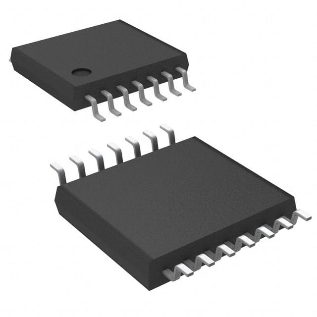
Viz Specifikace pro podrobnosti o produktu.

Encyclopedia Entry: 74VHCT126ATTR
Product Overview
- Category: Integrated Circuit (IC)
- Use: Logic Gate Buffer/Driver
- Characteristics: High-Speed, Low-Power, TTL-Compatible
- Package: TSSOP-14 (Thin Shrink Small Outline Package)
- Essence: Buffer/Driver IC with Quad Channels
- Packaging/Quantity: Typically sold in reels of 2500 units
Specifications
- Supply Voltage Range: 2.0V to 5.5V
- Input Voltage Range: 0V to Vcc
- Output Voltage Range: 0V to Vcc
- Maximum Operating Frequency: 125 MHz
- Propagation Delay Time: 4.3 ns (typical)
- Output Current: ±8 mA (source/sink)
Detailed Pin Configuration
The 74VHCT126ATTR IC has a total of 14 pins, which are assigned as follows:
- Pin 1: Input (Channel 1)
- Pin 2: Output (Channel 1)
- Pin 3: Enable (Channel 1)
- Pin 4: Ground (GND)
- Pin 5: Output (Channel 2)
- Pin 6: Input (Channel 2)
- Pin 7: Enable (Channel 2)
- Pin 8: Vcc (Supply Voltage)
- Pin 9: Output (Channel 3)
- Pin 10: Input (Channel 3)
- Pin 11: Enable (Channel 3)
- Pin 12: Output (Channel 4)
- Pin 13: Input (Channel 4)
- Pin 14: Enable (Channel 4)
Functional Features
- Quad-channel buffer/driver with independent enable control for each channel.
- TTL-compatible inputs and outputs, allowing seamless integration with existing TTL logic systems.
- High-speed operation with a maximum frequency of 125 MHz.
- Low-power consumption, making it suitable for battery-powered devices.
- Robust design with protection against electrostatic discharge (ESD).
Advantages
- Provides signal buffering and driving capabilities, enhancing the performance of digital circuits.
- Enables interfacing between different logic families due to its TTL compatibility.
- Offers high-speed operation, facilitating rapid data transmission.
- Low-power consumption extends battery life in portable electronic devices.
- ESD protection ensures reliability and longevity of the IC.
Disadvantages
- Limited number of channels (4), which may not be sufficient for complex systems requiring more inputs/outputs.
- May not be compatible with non-TTL logic families, requiring additional level-shifting circuitry.
Working Principles
The 74VHCT126ATTR is a buffer/driver IC that amplifies and controls the signals passing through its four independent channels. Each channel consists of an input buffer, an output driver, and an enable control. When the enable input is high, the corresponding channel is active, allowing the input signal to pass through to the output. Conversely, when the enable input is low, the output is in a high-impedance state, effectively disconnecting it from the input.
Detailed Application Field Plans
The 74VHCT126ATTR IC finds applications in various fields, including: 1. Digital communication systems 2. Microcontrollers and microprocessors 3. Industrial automation 4. Automotive electronics 5. Consumer electronics
Detailed Alternative Models
Alternative models that offer similar functionality to the 74VHCT126ATTR IC include: 1. SN74LVC126A: Quad Buffer/Driver with 3-State Outputs 2. MC74VHC126: Quad Bus Buffer Gate with 3-State Outputs 3. CD74HCT126: High-Speed CMOS Logic Quad Buffer with 3-State Outputs
(Note: The above alternative models are provided for reference and may have slight variations in specifications and pin configuration.)
In conclusion, the 74VHCT126ATTR is a quad-channel buffer/driver IC that offers high-speed operation, low-power consumption, and TTL compatibility. Its versatile applications make it suitable for various fields, while alternative models provide flexibility in design choices.
Seznam 10 běžných otázek a odpovědí souvisejících s aplikací 74VHCT126ATTR v technických řešeních
Sure! Here are 10 common questions and answers related to the application of 74VHCT126ATTR in technical solutions:
Q: What is the purpose of the 74VHCT126ATTR? A: The 74VHCT126ATTR is a quad buffer/line driver IC used for signal buffering and level shifting in digital circuits.
Q: What voltage levels can the 74VHCT126ATTR handle? A: The 74VHCT126ATTR is designed to work with TTL (Transistor-Transistor Logic) voltage levels, typically operating at 5V.
Q: How many buffers/drivers are there in the 74VHCT126ATTR? A: The 74VHCT126ATTR has four independent buffer/driver channels.
Q: Can the 74VHCT126ATTR be used for bidirectional communication? A: No, the 74VHCT126ATTR is unidirectional and can only drive signals in one direction.
Q: What is the maximum output current that the 74VHCT126ATTR can provide? A: The 74VHCT126ATTR can source or sink up to 8mA of current per channel.
Q: Is the 74VHCT126ATTR compatible with CMOS logic levels? A: Yes, the 74VHCT126ATTR is designed to be compatible with both TTL and CMOS logic levels.
Q: Can the 74VHCT126ATTR tolerate overvoltage on its inputs? A: No, the 74VHCT126ATTR has limited tolerance for overvoltage conditions and may get damaged if exceeded.
Q: What is the typical propagation delay of the 74VHCT126ATTR? A: The typical propagation delay of the 74VHCT126ATTR is around 6 nanoseconds.
Q: Can the 74VHCT126ATTR be used in high-speed applications? A: While the 74VHCT126ATTR is not specifically designed for high-speed applications, it can still be used in moderate-speed circuits.
Q: Are there any specific precautions to consider when using the 74VHCT126ATTR? A: It is important to ensure proper decoupling capacitors are used near the power supply pins and to avoid exceeding the maximum ratings specified in the datasheet.
Please note that these answers are general and may vary depending on the specific implementation and requirements of your technical solution. Always refer to the datasheet and consult with an expert for accurate information.

