

Viz Specifikace pro podrobnosti o produktu.
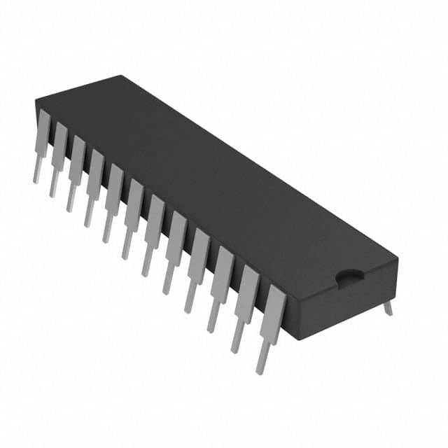
CD4034BE
Product Overview
- Category: Integrated Circuit (IC)
- Use: Shift Register
- Characteristics: Serial-In, Parallel-Out (SIPO) shift register with 8-bit storage capability
- Package: DIP (Dual In-line Package)
- Essence: The CD4034BE is a CMOS IC that can store and shift data in an electronic circuit.
- Packaging/Quantity: Available in tubes of 25 or reels of 1000 units.
Specifications
- Supply Voltage: 3V to 18V
- Logic Family: CMOS
- Number of Bits: 8
- Clock Frequency: Up to 5 MHz
- Operating Temperature Range: -55°C to +125°C
- Output Current: ±6mA
- Input Capacitance: 10pF
- Propagation Delay: 60ns
Pin Configuration
The CD4034BE has a total of 16 pins. Here is the detailed pin configuration:
- Clock (CLK)
- Clock Enable (CE)
- Serial Data Input (SER)
- Reset (RST)
- Output Enable (OE)
- Q0 (Output 0)
- Q1 (Output 1)
- Q2 (Output 2)
- Q3 (Output 3)
- Q4 (Output 4)
- Q5 (Output 5)
- Q6 (Output 6)
- Q7 (Output 7)
- VDD (Supply Voltage)
- Ground (GND)
- Carry Out (COUT)
Functional Features
- Serial-in, parallel-out operation
- Asynchronous reset function
- Buffered outputs for driving external loads
- Wide operating voltage range
- Low power consumption
- High noise immunity
- Easy cascading of multiple devices
Advantages and Disadvantages
Advantages
- Simple and straightforward operation
- Versatile in various digital applications
- Low power consumption
- Wide operating voltage range allows compatibility with different systems
- High noise immunity ensures reliable performance
Disadvantages
- Limited storage capacity (8 bits)
- Propagation delay may affect timing-sensitive applications
- Requires additional components for cascading multiple devices
Working Principles
The CD4034BE is a shift register that can store and shift data. It operates based on the clock signal received at the CLK pin. When the clock is triggered, the input data at the SER pin is shifted into the first stage of the register. The existing data in each stage is then shifted to the next stage, allowing new data to be stored.
The CE pin enables or disables the clock input, while the RST pin resets the register to its initial state. The OE pin controls the output buffer, enabling or disabling the outputs. The COUT pin provides a carry-out signal when cascading multiple devices.
Detailed Application Field Plans
The CD4034BE is commonly used in various digital applications, including:
- LED Displays: The shift register can control multiple LEDs, allowing dynamic display patterns.
- Digital Counters: By cascading multiple CD4034BE devices, complex counting sequences can be achieved.
- Data Storage: The register can temporarily store data during transmission or processing.
- Serial-to-Parallel Conversion: The serial input can be converted into parallel outputs for further processing.
Alternative Models
Here are some alternative models that provide similar functionality:
- SN74HC595N
- CD4015BE
- 74LS164
- CD4094BE
- CD4021BE
These alternatives offer different specifications and pin configurations, providing flexibility for various design requirements.
In conclusion, the CD4034BE is a versatile shift register IC with 8-bit storage capability. Its simple operation, low power consumption, and wide voltage range make it suitable for various digital applications. However, its limited storage capacity and propagation delay should be considered in timing-sensitive designs.
Seznam 10 běžných otázek a odpovědí souvisejících s aplikací CD4034BE v technických řešeních
Sure! Here are 10 common questions and answers related to the application of CD4034BE in technical solutions:
Q: What is CD4034BE? A: CD4034BE is a 8-bit static shift register IC (Integrated Circuit) commonly used in digital electronics.
Q: What are the main features of CD4034BE? A: CD4034BE features include parallel or serial input, serial output, synchronous or asynchronous operation, and cascading capability.
Q: How can CD4034BE be used in technical solutions? A: CD4034BE can be used for various applications such as data storage, LED matrix control, digital counters, and serial-to-parallel conversion.
Q: What is the maximum clock frequency supported by CD4034BE? A: CD4034BE can support clock frequencies up to 6 MHz.
Q: Can CD4034BE operate with both 3.3V and 5V power supplies? A: Yes, CD4034BE is compatible with both 3.3V and 5V power supply voltages.
Q: How many CD4034BE ICs can be cascaded together? A: Multiple CD4034BE ICs can be cascaded together to expand the number of outputs. Up to 32 ICs can be cascaded, providing a total of 256 outputs.
Q: Does CD4034BE have built-in latches for data storage? A: Yes, CD4034BE has built-in latches that allow data to be stored and held until new data is received.
Q: Can CD4034BE be used in both parallel and serial input modes? A: Yes, CD4034BE can be used in either parallel or serial input mode, depending on the application requirements.
Q: What is the maximum voltage that CD4034BE can handle? A: CD4034BE can handle a maximum voltage of 18V.
Q: Are there any specific precautions to consider when using CD4034BE? A: It is important to ensure proper power supply decoupling and avoid exceeding the maximum voltage and clock frequency ratings to prevent damage to the IC.
Please note that these answers are general and may vary based on specific datasheet specifications and application requirements.