Viz Specifikace pro podrobnosti o produktu.

CDCVF2310MPWREP
Overview
Category
CDCVF2310MPWREP belongs to the category of integrated circuits (ICs).
Use
It is commonly used as a clock driver in electronic devices.
Characteristics
- High-speed clock driver
- Low power consumption
- Small package size
- Wide operating voltage range
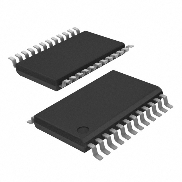
Package
CDCVF2310MPWREP is available in a small form factor package, typically in a QFN (Quad Flat No-leads) package.
Essence
The essence of CDCVF2310MPWREP lies in its ability to provide precise and stable clock signals for various electronic applications.
Packaging/Quantity
CDCVF2310MPWREP is usually packaged in reels or trays, with a typical quantity of 2500 units per reel.
Specifications and Parameters
- Operating Voltage Range: 1.8V - 3.3V
- Output Frequency Range: 10MHz - 200MHz
- Input Clock Signal Formats: LVCMOS, LVTTL
- Output Clock Signal Format: LVCMOS
- Number of Outputs: 10
- Operating Temperature Range: -40°C to +85°C
Pin Configuration
For detailed and complete pin configuration information, please refer to the datasheet provided by the manufacturer.
Functional Characteristics
CDCVF2310MPWREP offers the following functional characteristics:
- High-speed clock signal generation
- Low jitter and skew
- Programmable output delay
- Power-down mode for reduced power consumption
- ESD protection on all pins
Advantages and Disadvantages
Advantages: - High-speed operation - Low power consumption - Wide operating voltage range - Precise and stable clock signals
Disadvantages: - Limited number of outputs - Requires external components for proper operation
Applicable Range of Products
CDCVF2310MPWREP is suitable for a wide range of electronic devices that require high-speed clock signal generation, such as:
- Microprocessors
- Digital signal processors
- Field-programmable gate arrays (FPGAs)
- Communication equipment
- Data storage devices
Working Principles
CDCVF2310MPWREP works by taking an input clock signal and amplifying it to provide multiple synchronized output clock signals. It utilizes internal circuitry to minimize jitter and skew, ensuring accurate timing for the connected devices.
Detailed Application Field Plans
CDCVF2310MPWREP can be used in various applications, including:
- Microprocessor-based systems: Provides precise clock signals for synchronous operation of the microprocessor and other peripherals.
- FPGA-based designs: Enables synchronization of multiple components within the FPGA, improving overall system performance.
- Communication equipment: Ensures accurate timing for data transmission and reception.
- Data storage devices: Facilitates reliable data read/write operations by providing stable clock signals.
- Test and measurement instruments: Supports precise timing requirements for accurate measurements.
Detailed Alternative Models
Some alternative models to CDCVF2310MPWREP include:
- CDCVF2310MWR
- CDCVF2310PW
- CDCVF2310PWR
Please refer to the manufacturer's documentation for detailed specifications and compatibility information.
5 Common Technical Questions and Answers
Q: What is the maximum operating frequency of CDCVF2310MPWREP? A: The maximum operating frequency is 200MHz.
Q: Can CDCVF2310MPWREP operate with a voltage below 1.8V? A: No, the minimum operating voltage is 1.8V.
Q: Does CDCVF2310MPWREP support differential clock inputs? A: No, it only supports LVCMOS and LVTTL clock signal formats.
Q: Can I use CDCVF2310MPWREP in automotive applications? A: No, it is not designed for automotive-grade applications.
Q: Is CDCVF2310MPWREP RoHS compliant? A: Yes, it is compliant with the Restriction of Hazardous Substances (RoHS) directive.

