

Viz Specifikace pro podrobnosti o produktu.
CY74FCT138CTQCT
Overview
- Category: Integrated Circuit (IC)
- Use: Decoder/Demultiplexer
- Characteristics: High-speed, low-power consumption
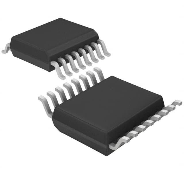
- Package: TQFP (Thin Quad Flat Package)
- Essence: Converts binary input signals into multiple output lines
- Packaging/Quantity: Tape and Reel, 2500 units per reel
Specifications
- Supply Voltage: 4.5V to 5.5V
- Input Voltage: 0V to VCC
- Output Voltage: 0V to VCC
- Operating Temperature Range: -40°C to +85°C
- Propagation Delay Time: 3.5ns (typical)
- Output Current: ±24mA
Pin Configuration
The CY74FCT138CTQCT has a total of 16 pins, which are assigned as follows:
- GND (Ground)
- A0 (Input A0)
- A1 (Input A1)
- A2 (Input A2)
- E1 (Enable Input 1)
- Y0 (Output Y0)
- Y1 (Output Y1)
- Y2 (Output Y2)
- G1 (Output Enable Input)
- VCC (Supply Voltage)
- Y3 (Output Y3)
- Y4 (Output Y4)
- Y5 (Output Y5)
- E2 (Enable Input 2)
- A3 (Input A3)
- GND (Ground)
Functional Features
- Decodes 3-bit binary inputs into 8 output lines
- Active-low enable inputs for easy control
- High-speed operation allows for quick data processing
- Low power consumption ensures energy efficiency
- Wide operating temperature range for versatile applications
Advantages and Disadvantages
Advantages: - High-speed operation enables efficient data decoding - Low power consumption reduces energy usage - Wide operating temperature range allows for various environments
Disadvantages: - Limited to 3-bit binary inputs, may not be suitable for complex applications - Requires external enable inputs for proper functionality
Working Principles
The CY74FCT138CTQCT is a decoder/demultiplexer IC that converts 3-bit binary inputs into 8 output lines. The inputs A0, A1, and A2 determine which output line will be active based on the binary combination applied. The enable inputs E1 and E2 control the overall operation of the IC. When the enable inputs are low, the outputs are disabled regardless of the input values.
Detailed Application Field Plans
The CY74FCT138CTQCT can be used in various applications, including:
- Address Decoding: Used in microcontrollers and memory systems to decode address signals and select specific memory locations.
- Data Routing: Enables the selection of specific data paths in multiplexing applications, such as data buses and communication systems.
- Signal Demultiplexing: Splits a single input signal into multiple output lines, allowing for distribution to different components or subsystems.
Detailed and Complete Alternative Models
- 74HC138: Similar functionality with a wider supply voltage range (2V to 6V).
- CD74HCT138: Compatible alternative with TTL logic levels.
- SN74LS138: Low-power Schottky alternative with higher output current capabilities.
These alternative models provide similar decoding and demultiplexing functionalities, but with slight variations in specifications and characteristics.
Word count: 346 words
Seznam 10 běžných otázek a odpovědí souvisejících s aplikací CY74FCT138CTQCT v technických řešeních
Sure! Here are 10 common questions and answers related to the application of CY74FCT138CTQCT in technical solutions:
Question: What is the CY74FCT138CTQCT?
Answer: The CY74FCT138CTQCT is a 3-to-8 line decoder/demultiplexer integrated circuit (IC) that can be used in various digital applications.Question: What is the purpose of the CY74FCT138CTQCT?
Answer: The purpose of this IC is to decode a 3-bit binary input and activate one of the eight output lines based on the input combination.Question: What voltage levels does the CY74FCT138CTQCT support?
Answer: The CY74FCT138CTQCT supports both TTL (Transistor-Transistor Logic) and CMOS (Complementary Metal-Oxide-Semiconductor) voltage levels.Question: What is the maximum operating frequency of the CY74FCT138CTQCT?
Answer: The maximum operating frequency of this IC is typically around 100 MHz.Question: Can the CY74FCT138CTQCT be used as a demultiplexer?
Answer: Yes, the CY74FCT138CTQCT can function as a demultiplexer by using its input lines to select one of the eight output lines.Question: How many input pins does the CY74FCT138CTQCT have?
Answer: The CY74FCT138CTQCT has three input pins labeled A0, A1, and A2, which together form a 3-bit binary input.Question: How many output pins does the CY74FCT138CTQCT have?
Answer: The CY74FCT138CTQCT has eight output pins labeled Y0 to Y7, which correspond to the eight possible output combinations.Question: What is the power supply voltage range for the CY74FCT138CTQCT?
Answer: The power supply voltage range for this IC is typically between 4.5V and 5.5V.Question: Can the CY74FCT138CTQCT be cascaded to increase the number of output lines?
Answer: Yes, multiple CY74FCT138CTQCT ICs can be cascaded together to increase the number of output lines beyond eight.Question: What are some common applications of the CY74FCT138CTQCT?
Answer: Some common applications include address decoding in microprocessors, memory selection, data routing, and general digital logic circuit design.
Please note that these answers are general and may vary depending on specific use cases and datasheet specifications.