

Viz Specifikace pro podrobnosti o produktu.
SN74ACT74NSR
Product Overview
- Category: Integrated Circuit (IC)
- Use: Flip-Flop
- Characteristics: High-speed, low-power consumption
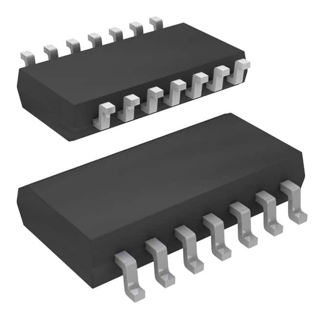
- Package: SOIC (Small Outline Integrated Circuit)
- Essence: Dual D-Type Positive-Edge-Triggered Flip-Flop
- Packaging/Quantity: Tape and Reel, 2500 units per reel
Specifications
- Supply Voltage Range: 4.5V to 5.5V
- High-Level Input Voltage: 2.0V min
- Low-Level Input Voltage: 0.8V max
- High-Level Output Voltage: 3.7V min
- Low-Level Output Voltage: 0.1V max
- Operating Temperature Range: -40°C to 85°C
Detailed Pin Configuration
The SN74ACT74NSR has a total of 14 pins, which are assigned as follows:
- CLR (Clear) - Clear input
- D (Data) - Data input
- CLK (Clock) - Clock input
- PR (Preset) - Preset input
- Q (Output) - Output
- Q̅ (Complementary Output) - Complementary output
- GND (Ground) - Ground reference
- Q̅ (Complementary Output) - Complementary output
- Q (Output) - Output
- VCC (Positive Power Supply) - Positive power supply
- D (Data) - Data input
- CLK (Clock) - Clock input
- PR (Preset) - Preset input
- CLR (Clear) - Clear input
Functional Features
The SN74ACT74NSR is a dual D-type positive-edge-triggered flip-flop. It operates at high speed while consuming low power. The flip-flop is designed to store and transfer data in electronic circuits. It can be used for various applications, such as data synchronization, frequency division, and digital signal processing.
Advantages and Disadvantages
Advantages: - High-speed operation - Low power consumption - Dual flip-flop configuration for increased functionality - Wide operating temperature range
Disadvantages: - Limited voltage supply range (4.5V to 5.5V) - Requires external clock signal for proper operation
Working Principles
The SN74ACT74NSR operates based on positive-edge-triggered flip-flop logic. When a rising edge is detected on the CLK input, the data present at the D input is transferred to the Q output. The complementary output, Q̅, represents the inverse of the Q output. The CLR and PR inputs allow for clearing or presetting the flip-flop to specific states.
Detailed Application Field Plans
The SN74ACT74NSR can be used in various applications, including:
- Data Synchronization: The flip-flop can be used to synchronize data signals in digital systems, ensuring accurate timing and preventing data corruption.
- Frequency Division: By utilizing multiple flip-flops, the IC can divide an input clock signal by factors of 2, creating frequency division circuits commonly used in digital counters and timers.
- Digital Signal Processing: The flip-flop can be employed in digital signal processing algorithms, such as storing intermediate results or buffering data during computations.
Detailed and Complete Alternative Models
- SN74ACT74D - Dual D-Type Positive-Edge-Triggered Flip-Flop in SOIC package
- CD4013BCN - Dual D-Type Flip-Flop with Set and Reset in DIP package
- MC74HC74AN - Dual D-Type Flip-Flop with Clear in PDIP package
- 74LS74 - Dual D-Type Positive-Edge-Triggered Flip-Flop in DIP package
These alternative models offer similar functionality and can be used as substitutes for the SN74ACT74NSR, depending on specific requirements.
In conclusion, the SN74ACT74NSR is a high-speed, low-power dual D-type positive-edge-triggered flip-flop. It finds applications in data synchronization, frequency division, and digital signal processing. With its compact SOIC package and wide operating temperature range, it provides a reliable solution for various electronic circuits.
Seznam 10 běžných otázek a odpovědí souvisejících s aplikací SN74ACT74NSR v technických řešeních
Sure! Here are 10 common questions and answers related to the application of SN74ACT74NSR:
Q: What is SN74ACT74NSR? A: SN74ACT74NSR is a dual D-type flip-flop integrated circuit (IC) that can store one bit of data in each flip-flop.
Q: What is the voltage supply range for SN74ACT74NSR? A: The voltage supply range for SN74ACT74NSR is typically between 4.5V and 5.5V.
Q: What is the maximum clock frequency supported by SN74ACT74NSR? A: SN74ACT74NSR can support clock frequencies up to 100 MHz.
Q: How many inputs and outputs does SN74ACT74NSR have? A: SN74ACT74NSR has two data inputs, two set inputs, two reset inputs, two clock inputs, and two complementary outputs.
Q: Can SN74ACT74NSR be used as a frequency divider? A: Yes, SN74ACT74NSR can be used as a frequency divider by connecting the output of one flip-flop to the clock input of another.
Q: What is the propagation delay of SN74ACT74NSR? A: The propagation delay of SN74ACT74NSR is typically around 7 ns.
Q: Is SN74ACT74NSR suitable for high-speed applications? A: Yes, SN74ACT74NSR is designed for high-speed operation and can be used in various high-frequency applications.
Q: Can SN74ACT74NSR be cascaded to create larger registers? A: Yes, multiple SN74ACT74NSR ICs can be cascaded together to create larger registers or shift registers.
Q: What is the power consumption of SN74ACT74NSR? A: The power consumption of SN74ACT74NSR is typically low, making it suitable for battery-powered applications.
Q: Are there any specific precautions to consider when using SN74ACT74NSR? A: It is important to ensure proper decoupling and bypass capacitors are used near the power supply pins to minimize noise and voltage fluctuations.
Please note that these answers are general and may vary depending on the specific application and datasheet of SN74ACT74NSR.