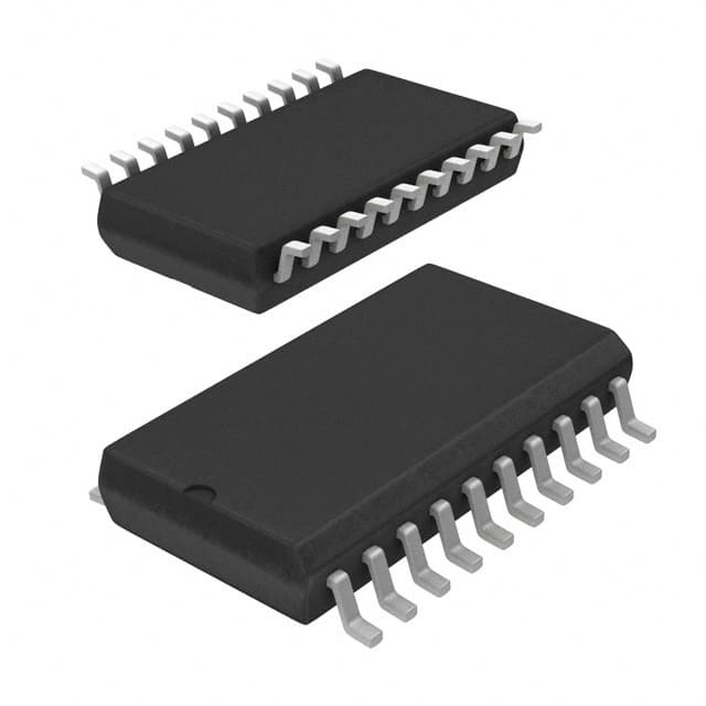
Viz Specifikace pro podrobnosti o produktu.

SN74ALS520DWG4
Product Overview
- Category: Integrated Circuit (IC)
- Use: Logic Gate
- Characteristics: Advanced Schottky TTL, 8-Bit Counter
- Package: SOIC (Small Outline Integrated Circuit)
- Essence: High-speed counter with asynchronous clear and parallel load
- Packaging/Quantity: Tape and Reel, 2500 units per reel
Specifications
- Supply Voltage Range: 4.5V to 5.5V
- Operating Temperature Range: -40°C to +85°C
- Input Current: ±1mA
- Output Current: ±8mA
- Propagation Delay Time: 9ns
- Counting Range: 0 to 255
- Clear Time: 20ns
- Load Time: 25ns
Detailed Pin Configuration
The SN74ALS520DWG4 has a total of 20 pins. The pin configuration is as follows:
- CLK (Clock Input)
- MR (Master Reset Input)
- CE (Count Enable Input)
- LD (Parallel Load Input)
- A0-A7 (Data Inputs)
- Q0-Q7 (Data Outputs)
- GND (Ground)
- VCC (Supply Voltage)
Functional Features
- High-speed operation: The SN74ALS520DWG4 operates at a high clock frequency, allowing for fast counting.
- Asynchronous clear: The master reset input (MR) allows the counter to be cleared asynchronously, independent of the clock signal.
- Parallel load: The parallel load input (LD) enables the counter to be loaded with data in parallel, rather than incrementing sequentially.
- Wide counting range: The counter can count from 0 to 255, providing flexibility in various applications.
Advantages and Disadvantages
Advantages: - High-speed operation allows for quick counting. - Asynchronous clear feature provides flexibility in resetting the counter. - Parallel load capability enables efficient data loading.
Disadvantages: - Limited counting range compared to some other counters. - Requires a stable power supply within the specified voltage range for optimal performance.
Working Principles
The SN74ALS520DWG4 is an 8-bit counter that operates based on the clock input (CLK). On each rising edge of the clock signal, the counter increments by one. The count enable input (CE) determines whether the counter is enabled or disabled. When CE is high, the counter counts; when CE is low, the counter holds its current value. The master reset input (MR) asynchronously clears the counter to zero when activated. The parallel load input (LD) allows the counter to be loaded with data in parallel, overriding the counting operation.
Detailed Application Field Plans
The SN74ALS520DWG4 can be used in various applications, including: 1. Digital frequency counters 2. Industrial automation systems 3. Communication equipment 4. Test and measurement instruments 5. Data processing systems
Detailed and Complete Alternative Models
- SN74ALS521DWG4: Similar to SN74ALS520DWG4 but with additional asynchronous preset capability.
- SN74ALS524DWG4: 8-bit counter with synchronous parallel load and asynchronous clear features.
- SN74ALS525DWG4: 8-bit counter with synchronous parallel load and synchronous clear features.
These alternative models offer similar functionality with slight variations to cater to specific application requirements.
Word count: 366 words
Seznam 10 běžných otázek a odpovědí souvisejících s aplikací SN74ALS520DWG4 v technických řešeních
Sure! Here are 10 common questions and answers related to the application of SN74ALS520DWG4 in technical solutions:
Q: What is SN74ALS520DWG4? A: SN74ALS520DWG4 is a specific model of integrated circuit (IC) commonly used in digital systems for data multiplexing applications.
Q: What are the key features of SN74ALS520DWG4? A: Some key features include 8-channel multiplexer, low power consumption, wide operating voltage range, and compatibility with TTL logic levels.
Q: How does SN74ALS520DWG4 work? A: It selects one of the eight input channels based on the control inputs and routes it to the output. The selected channel's data appears at the output.
Q: What is the maximum operating frequency of SN74ALS520DWG4? A: The maximum operating frequency of SN74ALS520DWG4 is typically around 25 MHz.
Q: Can SN74ALS520DWG4 handle analog signals? A: No, SN74ALS520DWG4 is designed to handle digital signals only. It is not suitable for analog signal processing.
Q: What is the power supply voltage range for SN74ALS520DWG4? A: SN74ALS520DWG4 operates within a power supply voltage range of 4.5V to 5.5V.
Q: Is SN74ALS520DWG4 compatible with other logic families? A: Yes, SN74ALS520DWG4 is compatible with TTL (Transistor-Transistor Logic) logic levels, making it easy to interface with other TTL-compatible devices.
Q: Can SN74ALS520DWG4 be used in high-speed applications? A: While SN74ALS520DWG4 is not specifically designed for high-speed applications, it can still be used in moderate-speed digital systems.
Q: What is the typical power consumption of SN74ALS520DWG4? A: The typical power consumption of SN74ALS520DWG4 is relatively low, making it suitable for battery-powered devices and energy-efficient designs.
Q: Are there any specific precautions to consider when using SN74ALS520DWG4? A: It is important to follow the manufacturer's datasheet and guidelines for proper handling, storage, and usage of SN74ALS520DWG4. Additionally, care should be taken to avoid exceeding the maximum ratings specified in the datasheet.
Please note that these answers are general and may vary depending on the specific application and requirements. Always refer to the manufacturer's datasheet for accurate and detailed information.

