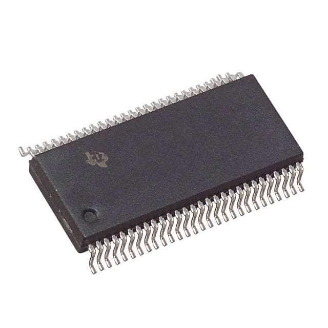
Viz Specifikace pro podrobnosti o produktu.

SN74ALVCH16271DLR
Product Overview
- Category: Integrated Circuit (IC)
- Use: Logic Level Translator
- Characteristics: High-speed, low-voltage, non-inverting
- Package: 56-pin TSSOP (Thin Shrink Small Outline Package)
- Essence: Translates signals between different voltage levels
- Packaging/Quantity: Tape and Reel, 2500 units per reel
Specifications
- Supply Voltage Range: 1.2V to 3.6V
- Input Voltage Range: 0V to VCC
- Output Voltage Range: 0V to VCC
- Maximum Operating Frequency: 400 MHz
- Number of Channels: 16
- Input/Output Type: Non-Inverting
- Propagation Delay: 2.5 ns (typical)
Detailed Pin Configuration
The SN74ALVCH16271DLR has a total of 56 pins. The pin configuration is as follows:
- OE (Output Enable) 1
- A1 (Input A1)
- B1 (Input B1)
- Y1 (Output Y1)
- GND (Ground)
- Y2 (Output Y2)
- B2 (Input B2)
- A2 (Input A2)
- OE (Output Enable) 2
- VCC (Supply Voltage)
- Y3 (Output Y3)
- B3 (Input B3)
- A3 (Input A3)
- OE (Output Enable) 3
- Y4 (Output Y4)
- B4 (Input B4)
- A4 (Input A4)
- OE (Output Enable) 4
- Y5 (Output Y5)
- B5 (Input B5)
- A5 (Input A5)
- OE (Output Enable) 5
- Y6 (Output Y6)
- B6 (Input B6)
- A6 (Input A6)
- OE (Output Enable) 6
- Y7 (Output Y7)
- B7 (Input B7)
- A7 (Input A7)
- OE (Output Enable) 7
- Y8 (Output Y8)
- B8 (Input B8)
- A8 (Input A8)
- OE (Output Enable) 8
- Y9 (Output Y9)
- B9 (Input B9)
- A9 (Input A9)
- OE (Output Enable) 9
- Y10 (Output Y10)
- B10 (Input B10)
- A10 (Input A10)
- OE (Output Enable) 10
- Y11 (Output Y11)
- B11 (Input B11)
- A11 (Input A11)
- OE (Output Enable) 11
- Y12 (Output Y12)
- B12 (Input B12)
- A12 (Input A12)
- OE (Output Enable) 12
- Y13 (Output Y13)
- B13 (Input B13)
- A13 (Input A13)
- OE (Output Enable) 13
- Y14 (Output Y14)
- VCC (Supply Voltage)
Functional Features
- High-speed logic level translation between different voltage domains
- Non-inverting operation preserves signal integrity
- Wide supply voltage range allows compatibility with various systems
- Low power consumption
- Schmitt-trigger inputs for noise immunity
Advantages and Disadvantages
Advantages: - High-speed operation enables efficient data transfer - Wide supply voltage range provides flexibility in system design - Non-inverting operation simplifies signal processing - Schmitt-trigger inputs enhance noise immunity
Disadvantages: - Limited number of channels (16) - Relatively large package size (56-pin TSSOP)
Working Principles
The SN74ALVCH16271DLR is a logic level translator that allows bidirectional voltage translation between two different voltage domains. It operates by receiving input signals from one voltage domain and translating them to the corresponding voltage levels in the other domain. The non-inverting nature of the device ensures that the output signals maintain the same logic state as the input signals.
The IC utilizes a combination of CMOS technology and Schottky diodes to achieve high-speed operation and low power consumption. The Schmitt-trigger inputs provide hysteresis, making the device less susceptible to noise and ensuring reliable signal translation.
Detailed Application Field Plans
The SN74ALVCH16271DLR can be used in various applications where voltage translation is required. Some potential application fields include
Seznam 10 běžných otázek a odpovědí souvisejících s aplikací SN74ALVCH16271DLR v technických řešeních
Sure! Here are 10 common questions and answers related to the application of SN74ALVCH16271DLR in technical solutions:
Q: What is SN74ALVCH16271DLR? A: SN74ALVCH16271DLR is a 16-bit transparent D-type latch with 3-state outputs, commonly used in digital systems.
Q: What is the operating voltage range for SN74ALVCH16271DLR? A: The operating voltage range for SN74ALVCH16271DLR is typically between 1.65V and 3.6V.
Q: Can SN74ALVCH16271DLR be used in both input and output applications? A: Yes, SN74ALVCH16271DLR can be used as both an input and output device in digital systems.
Q: What is the maximum data rate supported by SN74ALVCH16271DLR? A: SN74ALVCH16271DLR supports high-speed operation with a maximum data rate of up to 400 MHz.
Q: How many 3-state outputs does SN74ALVCH16271DLR have? A: SN74ALVCH16271DLR has 16 3-state outputs, one for each bit of the latch.
Q: Can SN74ALVCH16271DLR be cascaded to create larger registers? A: Yes, multiple SN74ALVCH16271DLR latches can be cascaded together to create larger registers or data storage units.
Q: Does SN74ALVCH16271DLR have any built-in protection features? A: Yes, SN74ALVCH16271DLR has built-in ESD protection to safeguard against electrostatic discharge.
Q: What is the power supply current consumption of SN74ALVCH16271DLR? A: The power supply current consumption of SN74ALVCH16271DLR is typically low, making it suitable for low-power applications.
Q: Can SN74ALVCH16271DLR be used in both commercial and industrial temperature ranges? A: Yes, SN74ALVCH16271DLR is designed to operate within both commercial (0°C to 70°C) and industrial (-40°C to 85°C) temperature ranges.
Q: Are there any specific layout considerations when using SN74ALVCH16271DLR? A: Yes, it is recommended to follow the manufacturer's guidelines for proper layout and decoupling capacitor placement to ensure optimal performance.
Please note that these answers are general and may vary depending on the specific application and requirements. It is always advisable to refer to the datasheet and consult with technical experts for accurate information.

