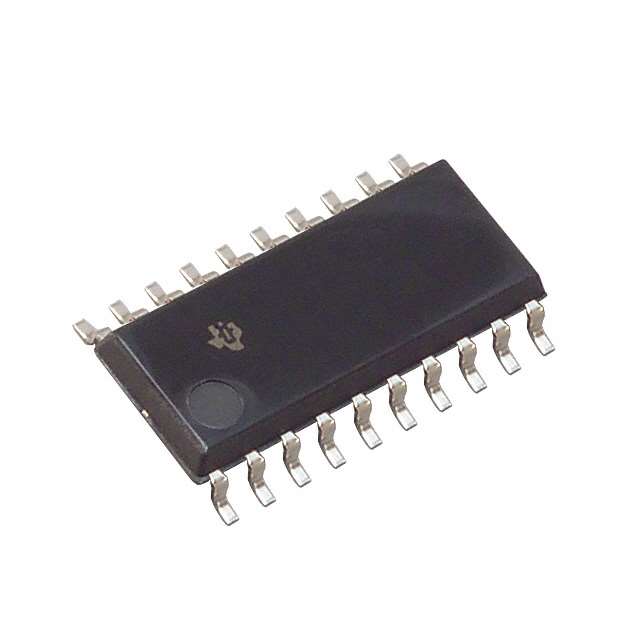
Viz Specifikace pro podrobnosti o produktu.

SN74AS638ANSR
Product Overview
- Category: Integrated Circuit
- Use: Logic Function
- Characteristics: High-speed, Low-power, TTL Compatible
- Package: SOIC (Small Outline Integrated Circuit)
- Essence: 8-Bit Binary Counter with Output Registers
- Packaging/Quantity: Tape and Reel, 2500 pieces per reel
Specifications
- Supply Voltage: 4.5V to 5.5V
- Operating Temperature Range: -40°C to +85°C
- Input Voltage Levels: TTL Compatible
- Output Voltage Levels: TTL Compatible
- Maximum Clock Frequency: 125 MHz
- Number of Pins: 20
- Pin Pitch: 1.27 mm
Detailed Pin Configuration
- CLK (Clock Input)
- MR (Master Reset Input)
- QA (Output A)
- QB (Output B)
- QC (Output C)
- QD (Output D)
- QE (Output E)
- QF (Output F)
- QG (Output G)
- QH (Output H)
- VCC (Supply Voltage)
- GND (Ground)
- CE (Clock Enable Input)
- P (Parallel Load Input)
- CP (Clock Pulse Input)
- DS (Serial Data Input)
- OE (Output Enable Input)
- SER (Serial Enable Input)
- QH' (Complement of Output H)
- QH'' (Complement of Output H')
Functional Features
- 8-bit binary counter with parallel load capability
- Outputs can be individually enabled or disabled
- Can operate as a synchronous or asynchronous counter
- Supports cascading multiple counters for larger word sizes
- Provides complementary outputs for each bit
Advantages
- High-speed operation allows for efficient data processing
- Low-power consumption for energy-efficient applications
- TTL compatibility ensures easy integration with existing systems
- Parallel load capability enables flexible data input
- Multiple counters can be cascaded for expanded functionality
Disadvantages
- Limited to 8-bit word size, may not be suitable for larger applications
- Requires careful consideration of clock frequency and timing constraints
- Sensitive to noise and voltage fluctuations, necessitating proper signal conditioning
Working Principles
The SN74AS638ANSR is an 8-bit binary counter with output registers. It operates by counting the number of clock pulses received at the CLK input. The counter can be reset to its initial state using the MR input. The parallel load input (P) allows for loading a specific value into the counter, while the clock enable input (CE) controls the counting operation. The outputs (QA to QH) represent the binary count, with complementary outputs (QH' and QH'') available for each bit.
Detailed Application Field Plans
The SN74AS638ANSR is commonly used in various digital systems that require counting and sequencing operations. Some potential application fields include:
Digital Counters: The IC can be utilized in electronic devices that require counting events, such as timers, frequency dividers, and pulse generators.
Data Processing: The counter's parallel load capability makes it suitable for applications involving data manipulation, such as arithmetic operations and data sorting.
Address Decoding: The IC can be employed in memory systems to decode addresses and select specific memory locations.
Control Systems: The counter can be integrated into control circuits to generate timing signals, synchronize operations, or implement state machines.
Detailed and Complete Alternative Models
- SN74LS638N: Similar to SN74AS638ANSR but operates at a lower clock frequency.
- SN74HC638N: CMOS version of the counter with improved noise immunity and lower power consumption.
- CD40193BE: 4-bit synchronous binary up/down counter with parallel load capability.
These alternative models offer similar functionality to the SN74AS638ANSR but may have different specifications or package options.
Word count: 498 words
Seznam 10 běžných otázek a odpovědí souvisejících s aplikací SN74AS638ANSR v technických řešeních
Sure! Here are 10 common questions and answers related to the application of SN74AS638ANSR in technical solutions:
Q: What is SN74AS638ANSR? A: SN74AS638ANSR is a specific model number for a digital multiplexer IC (integrated circuit) manufactured by Texas Instruments.
Q: What is the purpose of a digital multiplexer? A: A digital multiplexer is used to select one of several input signals and route it to a single output based on control inputs.
Q: What are the key features of SN74AS638ANSR? A: SN74AS638ANSR is a 1-of-8 digital multiplexer with 3-state outputs, which means it can select one of eight inputs and provide the selected signal as an output.
Q: What is the voltage range supported by SN74AS638ANSR? A: SN74AS638ANSR supports a voltage range of 4.5V to 5.5V.
Q: How many control inputs does SN74AS638ANSR have? A: SN74AS638ANSR has three control inputs, typically labeled A, B, and C.
Q: What is the maximum operating frequency of SN74AS638ANSR? A: The maximum operating frequency of SN74AS638ANSR is typically around 25 MHz.
Q: Can SN74AS638ANSR be used in both digital and analog applications? A: No, SN74AS638ANSR is specifically designed for digital applications and should not be used in analog circuits.
Q: What is the power supply requirement for SN74AS638ANSR? A: SN74AS638ANSR requires a single power supply voltage of 5V.
Q: Can SN74AS638ANSR handle bidirectional signals? A: No, SN74AS638ANSR is a unidirectional multiplexer and can only route signals from inputs to the output.
Q: Are there any recommended applications for SN74AS638ANSR? A: SN74AS638ANSR can be used in various applications such as data routing, signal selection, address decoding, and bus switching in digital systems.
Please note that these answers are general and may vary depending on the specific requirements and use cases. It's always recommended to refer to the datasheet and consult with technical experts for accurate information.

