

Viz Specifikace pro podrobnosti o produktu.
SN74AS74ANSR
Product Overview
- Category: Integrated Circuit (IC)
- Use: Flip-Flop
- Characteristics: Dual D-Type Positive-Edge-Triggered Flip-Flop
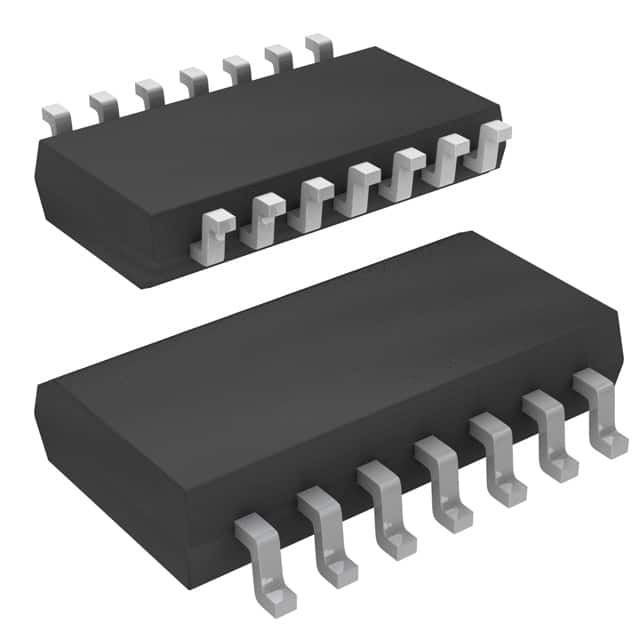
- Package: SOIC (Small Outline Integrated Circuit)
- Essence: Sequential Logic Device
- Packaging/Quantity: Tape and Reel, 2500 pieces per reel
Specifications
- Supply Voltage Range: 4.5V to 5.5V
- High-Level Input Voltage: 2.0V to VCC
- Low-Level Input Voltage: GND to 0.8V
- High-Level Output Voltage: VCC - 0.5V
- Low-Level Output Voltage: 0.5V
- Maximum Clock Frequency: 100MHz
- Propagation Delay Time: 10ns
- Operating Temperature Range: -40°C to +85°C
Detailed Pin Configuration
The SN74AS74ANSR has a total of 14 pins. The pin configuration is as follows:
- CLR (Clear) - Active LOW clear input
- D (Data) - Data input for the flip-flop
- CLK (Clock) - Clock input for triggering the flip-flop
- PR (Preset) - Active LOW preset input
- Q (Output) - Complementary output
- Q̅ (Output) - True output
- GND (Ground) - Ground reference
- Q̅ (Output) - True output
- Q (Output) - Complementary output
- VCC (Supply Voltage) - Positive power supply
- D (Data) - Data input for the flip-flop
- CLK (Clock) - Clock input for triggering the flip-flop
- PR (Preset) - Active LOW preset input
- CLR (Clear) - Active LOW clear input
Functional Features
The SN74AS74ANSR is a dual D-type positive-edge-triggered flip-flop. It is designed to store and transfer data in sequential logic circuits. The flip-flop operates on the rising edge of the clock signal, capturing the data input and storing it in its internal memory. The complementary outputs provide both true and inverted versions of the stored data.
Advantages and Disadvantages
Advantages: - Dual flip-flop in a single package saves board space - Positive-edge triggering ensures reliable operation - Wide operating temperature range allows for various applications - Fast propagation delay time enables high-speed operation
Disadvantages: - Limited supply voltage range may restrict certain applications - Only supports positive-edge triggering, not suitable for negative-edge triggered systems
Working Principles
The SN74AS74ANSR flip-flop works based on the positive-edge-triggered D-type flip-flop principle. When the clock signal transitions from low to high (rising edge), the data input is sampled and stored in the flip-flop's internal memory. The stored data is then available at the complementary outputs. The clear and preset inputs allow for resetting or setting the flip-flop to a specific state.
Detailed Application Field Plans
The SN74AS74ANSR flip-flop finds applications in various digital systems where sequential logic is required. Some potential application fields include:
- Counters and Registers: The flip-flop can be used as building blocks for designing counters and registers in digital circuits.
- State Machines: Sequential circuits like state machines utilize flip-flops to store and transition between different states based on input conditions.
- Data Storage: The flip-flop can be used to store temporary data in microcontrollers, microprocessors, and other digital systems.
- Clock Synchronization: Flip-flops are commonly used in clock synchronization circuits to ensure proper timing and synchronization of signals.
Detailed and Complete Alternative Models
- SN74AS74ADR: Similar dual D-type positive-edge-triggered flip-flop, but available in a different package (SOIC-14).
- CD4013BCN: Dual D-type flip-flop with complementary outputs, available in a 14-pin DIP package.
- MC74HC74AN: Dual D-type flip-flop with preset and clear inputs, available in a 14-pin DIP package.
These alternative models provide similar functionality and can be used as substitutes for the SN74AS74ANSR in various applications.
Word count: 511 words
Seznam 10 běžných otázek a odpovědí souvisejících s aplikací SN74AS74ANSR v technických řešeních
Sure! Here are 10 common questions and answers related to the application of SN74AS74ANSR in technical solutions:
Question: What is SN74AS74ANSR?
- Answer: SN74AS74ANSR is a dual D-type flip-flop integrated circuit (IC) that can be used in various digital applications.Question: What is the operating voltage range for SN74AS74ANSR?
- Answer: The operating voltage range for SN74AS74ANSR is typically between 4.5V and 5.5V.Question: What is the maximum clock frequency supported by SN74AS74ANSR?
- Answer: SN74AS74ANSR can support clock frequencies up to 100 MHz.Question: How many flip-flops are there in SN74AS74ANSR?
- Answer: SN74AS74ANSR contains two independent D-type flip-flops.Question: What is the output drive capability of SN74AS74ANSR?
- Answer: SN74AS74ANSR has a standard output drive capability of 8 mA.Question: Can SN74AS74ANSR be used in both synchronous and asynchronous applications?
- Answer: Yes, SN74AS74ANSR can be used in both synchronous and asynchronous applications.Question: What is the typical propagation delay of SN74AS74ANSR?
- Answer: The typical propagation delay of SN74AS74ANSR is around 12 ns.Question: Is SN74AS74ANSR compatible with other logic families?
- Answer: Yes, SN74AS74ANSR is compatible with TTL (Transistor-Transistor Logic) and CMOS (Complementary Metal-Oxide-Semiconductor) logic families.Question: Can SN74AS74ANSR be used in high-speed applications?
- Answer: Yes, SN74AS74ANSR is designed for high-speed operation and can be used in such applications.Question: What are some common applications of SN74AS74ANSR?
- Answer: SN74AS74ANSR is commonly used in counters, registers, shift registers, frequency dividers, and other digital circuits where flip-flops are required.
Please note that the answers provided here are general and may vary depending on specific datasheet specifications and application requirements.