Viz Specifikace pro podrobnosti o produktu.

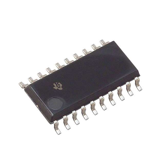
SN74AS757NSR
Product Overview
- Category: Integrated Circuit (IC)
- Use: Logic Gate
- Characteristics: High-speed, low-power consumption
- Package: Surface Mount Technology (SMT)
- Essence: 8-bit Shift Register with Output Latches
- Packaging/Quantity: Tape and Reel, 2500 units per reel
Specifications
- Supply Voltage Range: 4.5V to 5.5V
- Input Voltage Range: 0V to VCC
- Operating Temperature Range: -40°C to +85°C
- Output Current: ±24mA
- Propagation Delay Time: 9ns (typical)
- Power Dissipation: 500mW (max)
Detailed Pin Configuration
The SN74AS757NSR has a total of 20 pins, which are assigned as follows:
- SER (Serial Data Input)
- CLK (Clock Input)
- RCLK (Register Clock Input)
- SRCLR (Shift Register Clear Input)
- OE (Output Enable Input)
- QA-QH (Parallel Outputs)
- GND (Ground)
- QH' (Serial Output)
- VCC (Supply Voltage)
Functional Features
- 8-bit parallel-in to serial-out shift register
- Output latches for holding the data
- Serial data input with synchronous clocking
- Shift register clear function
- Output enable control for tri-state outputs
Advantages and Disadvantages
Advantages: - High-speed operation allows for efficient data transfer - Low power consumption helps in reducing energy usage - Compact SMT package enables space-saving designs - Output latches provide stable data storage
Disadvantages: - Limited voltage range may restrict certain applications - Propagation delay time may affect timing-sensitive operations - Not suitable for high-current applications due to limited output current
Working Principles
The SN74AS757NSR is an 8-bit shift register with output latches. It operates by receiving parallel data through the SER pin and shifting it out serially through the QH' pin. The CLK input synchronizes the shifting process, while the RCLK input controls the transfer of data from the shift register to the output latches. The SRCLR input clears the shift register, and the OE input enables or disables the outputs.
Detailed Application Field Plans
The SN74AS757NSR can be used in various applications, including: 1. Serial data transmission systems 2. Data storage and retrieval systems 3. Digital communication devices 4. Control systems requiring sequential data processing 5. Microcontroller-based projects
Detailed and Complete Alternative Models
- SN74LS757: Similar functionality but operates at a lower speed.
- SN74HC757: Compatible with CMOS logic levels and has a wider voltage range.
- SN74F757: Faster operation with reduced power consumption.
These alternative models offer similar functionalities to the SN74AS757NSR but may have different specifications and characteristics.
Word count: 386 words
Seznam 10 běžných otázek a odpovědí souvisejících s aplikací SN74AS757NSR v technických řešeních
Sure! Here are 10 common questions and answers related to the application of SN74AS757NSR in technical solutions:
Q: What is SN74AS757NSR? A: SN74AS757NSR is a specific integrated circuit (IC) chip manufactured by Texas Instruments. It is a dual 4-to-1 multiplexer with three-state outputs.
Q: What is the purpose of SN74AS757NSR? A: The purpose of this IC is to provide a convenient way to select one of four input signals and route it to an output line based on control inputs.
Q: What are the key features of SN74AS757NSR? A: Some key features include low power consumption, wide operating voltage range, fast switching speed, and compatibility with TTL logic levels.
Q: How can I use SN74AS757NSR in my circuit design? A: You can use this IC to implement signal routing, data selection, or multiplexing functions in your circuit design.
Q: What is the maximum operating frequency of SN74AS757NSR? A: The maximum operating frequency of this IC is typically around 25 MHz.
Q: Can SN74AS757NSR handle both analog and digital signals? A: No, SN74AS757NSR is designed to work with digital signals only. It is not suitable for handling analog signals.
Q: What is the power supply voltage range for SN74AS757NSR? A: The recommended power supply voltage range for this IC is typically between 4.5V and 5.5V.
Q: Does SN74AS757NSR have any built-in protection features? A: Yes, this IC has built-in diode protection on all inputs and outputs to prevent damage from electrostatic discharge (ESD).
Q: Can I cascade multiple SN74AS757NSR ICs together? A: Yes, you can cascade multiple ICs to increase the number of input signals that can be selected.
Q: Where can I find more information about SN74AS757NSR? A: You can refer to the datasheet provided by Texas Instruments for detailed information about the electrical characteristics, pin configuration, and application examples of SN74AS757NSR.
Please note that the answers provided here are general and may vary depending on specific circuit requirements and application scenarios.

