

Viz Specifikace pro podrobnosti o produktu.
SN74AS825ANTG4
Product Overview
- Category: Integrated Circuit
- Use: Logic Gate
- Characteristics: High-speed, low-power, 8-bit latch/shift register
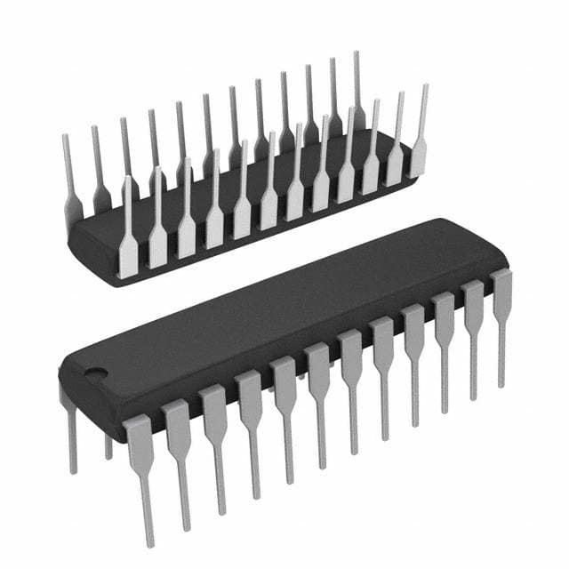
- Package: SOIC (Small Outline Integrated Circuit)
- Essence: Combines the functionality of a latch and a shift register in a single chip
- Packaging/Quantity: Tape and Reel, 2500 units per reel
Specifications
- Supply Voltage Range: 4.5V to 5.5V
- Operating Temperature Range: -40°C to 85°C
- Input/Output Compatibility: TTL (Transistor-Transistor Logic) compatible
- Number of Bits: 8
- Logic Family: AS (Advanced Schottky)
Detailed Pin Configuration
The SN74AS825ANTG4 has a total of 20 pins. The pin configuration is as follows:
- GND (Ground)
- D0 (Data Input 0)
- D1 (Data Input 1)
- D2 (Data Input 2)
- D3 (Data Input 3)
- D4 (Data Input 4)
- D5 (Data Input 5)
- D6 (Data Input 6)
- D7 (Data Input 7)
- CLK (Clock Input)
- MR (Master Reset Input)
- Q0 (Serial Output 0)
- Q1 (Serial Output 1)
- Q2 (Serial Output 2)
- Q3 (Serial Output 3)
- Q4 (Serial Output 4)
- Q5 (Serial Output 5)
- Q6 (Serial Output 6)
- Q7 (Serial Output 7)
- VCC (Supply Voltage)
Functional Features
- Latch Function: The SN74AS825ANTG4 can store data at its inputs and hold it until the latch is cleared.
- Shift Register Function: It can shift the stored data serially from one output to another upon receiving clock pulses.
- Master Reset: The MR input allows resetting the latch/shift register to its initial state.
- Serial Output: The Q0-Q7 outputs provide the shifted data in a serial format.
Advantages and Disadvantages
Advantages: - High-speed operation - Low power consumption - Compact integration of latch and shift register functionality
Disadvantages: - Limited number of bits (8) - Restricted operating temperature range (-40°C to 85°C)
Working Principles
The SN74AS825ANTG4 operates based on the principles of latch and shift register. When the latch enable input (LE) is high, the data at the D0-D7 inputs is latched and stored. The stored data can be shifted out through the Q0-Q7 outputs by providing clock pulses at the CLK input. The master reset input (MR) clears the latch and shift register, returning them to their initial state.
Detailed Application Field Plans
The SN74AS825ANTG4 finds applications in various fields where data storage and serial data transmission are required. Some potential application areas include:
- Communication Systems: Used for data buffering and serial data transmission in communication protocols.
- Industrial Automation: Employed in control systems for storing and shifting data between different modules.
- Consumer Electronics: Integrated into devices requiring data storage and serial data transfer, such as gaming consoles and digital cameras.
- Automotive Electronics: Utilized in automotive control units for data processing and transmission.
- Medical Equipment: Incorporated in medical devices for data handling and communication purposes.
Detailed and Complete Alternative Models
- SN74AS825A: Similar functionality with minor variations in specifications.
- SN74LS595: 8-bit shift register with output latches.
- CD4094B: 8-bit serial-in, parallel-out shift register with output latches.
These alternative models provide similar latch and shift register functionality, catering to different requirements and specifications.
Word count: 446 words
Seznam 10 běžných otázek a odpovědí souvisejících s aplikací SN74AS825ANTG4 v technických řešeních
Sure! Here are 10 common questions and answers related to the application of SN74AS825ANTG4 in technical solutions:
Q: What is the SN74AS825ANTG4? A: The SN74AS825ANTG4 is a quad 2-input positive-NAND gate IC (integrated circuit) that can be used in various digital logic applications.
Q: What is the operating voltage range for SN74AS825ANTG4? A: The operating voltage range for SN74AS825ANTG4 is typically between 4.5V and 5.5V.
Q: What is the maximum output current of SN74AS825ANTG4? A: The maximum output current of SN74AS825ANTG4 is 8mA.
Q: Can SN74AS825ANTG4 be used as a level shifter? A: Yes, SN74AS825ANTG4 can be used as a level shifter to convert signals between different voltage levels.
Q: What is the propagation delay of SN74AS825ANTG4? A: The propagation delay of SN74AS825ANTG4 is typically around 9 ns.
Q: Is SN74AS825ANTG4 suitable for high-speed applications? A: Yes, SN74AS825ANTG4 is designed for high-speed operation and can be used in applications with fast switching requirements.
Q: Can SN74AS825ANTG4 be used in both CMOS and TTL logic systems? A: Yes, SN74AS825ANTG4 is compatible with both CMOS and TTL logic families.
Q: Does SN74AS825ANTG4 have built-in protection against electrostatic discharge (ESD)? A: Yes, SN74AS825ANTG4 has built-in ESD protection to safeguard against damage during handling and operation.
Q: Can SN74AS825ANTG4 be used in automotive applications? A: Yes, SN74AS825ANTG4 is qualified for automotive applications and can operate within the specified temperature range.
Q: What is the package type of SN74AS825ANTG4? A: SN74AS825ANTG4 is available in a small-outline integrated circuit (SOIC) package with 14 pins.
Please note that the answers provided here are general and may vary depending on specific datasheet specifications and application requirements.