

Viz Specifikace pro podrobnosti o produktu.
SN74AUC1G17YZPR
Product Overview
- Category: Integrated Circuit (IC)
- Use: Logic Gate
- Characteristics: Single Schmitt-Trigger Buffer/Driver
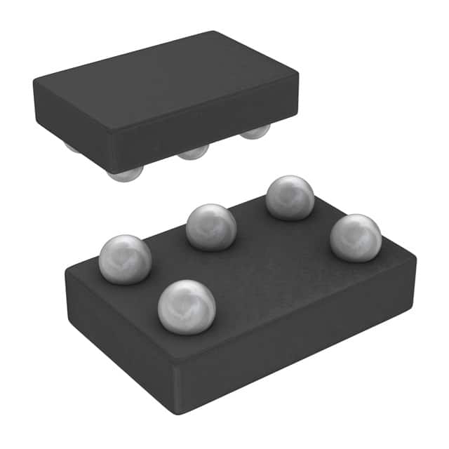
- Package: 5-Pin SOT-553
- Essence: High-speed CMOS technology
- Packaging/Quantity: Tape and Reel, 3000 pieces per reel
Specifications
- Supply Voltage Range: 0.8V to 3.6V
- Input Voltage Range: -0.5V to VCC + 0.5V
- Output Voltage Range: 0V to VCC
- Maximum Operating Frequency: 500 MHz
- Propagation Delay: 2.9 ns (typical)
- Low Power Consumption: 0.9 µA (typical)
Detailed Pin Configuration
The SN74AUC1G17YZPR has the following pin configuration:
```
| | --|1 5|-- --|2 4|-- --|3___| ```
Pin 1: Input (A) Pin 2: Ground (GND) Pin 3: Output (Y) Pin 4: Not Connected (NC) Pin 5: Power Supply (VCC)
Functional Features
- Single Schmitt-trigger buffer/driver with open-drain output
- Provides signal conditioning and level shifting capabilities
- Wide supply voltage range allows compatibility with various systems
- High-speed operation suitable for applications requiring fast switching times
- Low power consumption extends battery life in portable devices
Advantages and Disadvantages
Advantages: - Small package size enables space-saving designs - Wide operating voltage range enhances versatility - High-speed performance meets demanding application requirements - Low power consumption reduces energy consumption
Disadvantages: - Limited number of input/output pins restricts complex circuit designs - Open-drain output may require additional pull-up resistor for certain applications
Working Principles
The SN74AUC1G17YZPR is a single Schmitt-trigger buffer/driver IC. It operates by receiving an input signal (A) and providing a conditioned output signal (Y). The Schmitt-trigger input ensures hysteresis, allowing the device to tolerate noisy or slow-changing input signals. The open-drain output configuration allows for flexible interfacing with other devices, requiring an external pull-up resistor to achieve logic high levels.
Detailed Application Field Plans
The SN74AUC1G17YZPR is commonly used in various electronic systems that require signal buffering, level shifting, and noise immunity. Some specific application fields include:
Communication Systems:
- Signal conditioning in data transmission lines
- Level shifting between different voltage domains
Industrial Control Systems:
- Interface between sensors and microcontrollers
- Noise rejection in harsh environments
Consumer Electronics:
- Signal buffering in audio amplifiers
- Level translation in battery-powered devices
Automotive Electronics:
- Signal conditioning in automotive communication networks
- Level shifting in vehicle control modules
Detailed and Complete Alternative Models
- SN74AUP1G17DCKR: Single Schmitt-trigger buffer/driver in SC-70 package
- SN74LVC1G17DBVR: Single Schmitt-trigger buffer/driver in SOT-23 package
- SN74LV1T17DBVR: Single Schmitt-trigger buffer/driver in SOT-23 package
These alternative models offer similar functionality and can be considered as replacements for the SN74AUC1G17YZPR in different package options.
Word count: 410 words
Seznam 10 běžných otázek a odpovědí souvisejících s aplikací SN74AUC1G17YZPR v technických řešeních
Sure! Here are 10 common questions and answers related to the application of SN74AUC1G17YZPR in technical solutions:
Q1: What is the SN74AUC1G17YZPR? A1: The SN74AUC1G17YZPR is a single Schmitt-trigger buffer/driver with open-drain output. It is commonly used in digital logic circuits.
Q2: What is the purpose of a Schmitt-trigger buffer/driver? A2: A Schmitt-trigger buffer/driver is used to convert weak or noisy input signals into clean, stable digital signals.
Q3: What is the voltage range supported by the SN74AUC1G17YZPR? A3: The SN74AUC1G17YZPR supports a wide voltage range from 0.8V to 3.6V.
Q4: Can the SN74AUC1G17YZPR handle high-speed signals? A4: Yes, the SN74AUC1G17YZPR is designed for high-speed operation, making it suitable for applications that require fast signal processing.
Q5: How many inputs does the SN74AUC1G17YZPR have? A5: The SN74AUC1G17YZPR has one input.
Q6: Does the SN74AUC1G17YZPR have an output enable pin? A6: No, the SN74AUC1G17YZPR does not have an output enable pin. The output is always enabled.
Q7: What is the maximum output current of the SN74AUC1G17YZPR? A7: The SN74AUC1G17YZPR can sink up to 32mA of current.
Q8: Can the SN74AUC1G17YZPR be used in both CMOS and TTL logic circuits? A8: Yes, the SN74AUC1G17YZPR is compatible with both CMOS and TTL logic levels.
Q9: What is the typical propagation delay of the SN74AUC1G17YZPR? A9: The typical propagation delay of the SN74AUC1G17YZPR is around 2.5ns.
Q10: What are some common applications of the SN74AUC1G17YZPR? A10: The SN74AUC1G17YZPR is commonly used in applications such as level shifting, signal conditioning, clock distribution, and interfacing between different logic families.
Please note that these answers are general and may vary depending on specific use cases and requirements.