

Viz Specifikace pro podrobnosti o produktu.
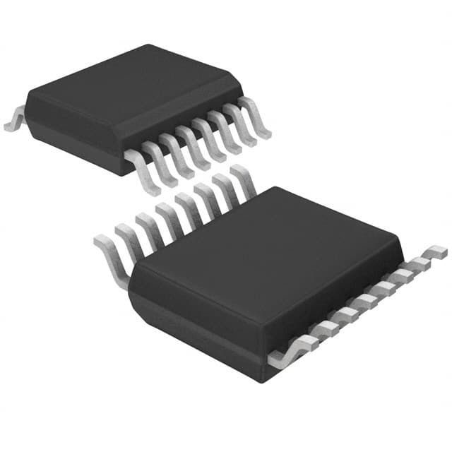
SN74HC165DBR
Product Overview
- Category: Integrated Circuit (IC)
- Use: Shift Register
- Characteristics: Serial-in, Parallel-out, 8-bit, High-Speed
- Package: SSOP-16
- Essence: Data storage and transfer
- Packaging/Quantity: Tape and Reel, 2500 units per reel
Specifications
- Supply Voltage Range: 2V to 6V
- Input Voltage Range: 0V to VCC
- Output Voltage Range: 0V to VCC
- Operating Temperature Range: -40°C to +85°C
- Maximum Clock Frequency: 100 MHz
- Maximum Data Transfer Rate: 400 Mbps
Detailed Pin Configuration
The SN74HC165DBR has a total of 16 pins. The pin configuration is as follows:
- SER (Serial Data Input)
- QA (Parallel Output A)
- QB (Parallel Output B)
- QC (Parallel Output C)
- QD (Parallel Output D)
- QE (Parallel Output E)
- QF (Parallel Output F)
- QG (Parallel Output G)
- QH (Parallel Output H)
- GND (Ground)
- CLK (Clock Input)
- SH/LD (Shift/Load Input)
- OE (Output Enable Input)
- DS (Serial Data Input)
- MR (Master Reset Input)
- VCC (Supply Voltage)
Functional Features
- Serial-in, parallel-out shift register operation
- 8-bit data storage and transfer
- High-speed clock input for fast data transfer
- Shift/Load input for selecting between shift and parallel load modes
- Output enable input for controlling the output state
- Master reset input for resetting the shift register
- Wide supply voltage range for flexibility in different applications
Advantages and Disadvantages
Advantages: - High-speed operation allows for quick data transfer - Versatile shift/load mode selection for different applications - Wide supply voltage range enables compatibility with various systems
Disadvantages: - Limited number of parallel outputs (8 bits) - Requires external clock signal for proper operation
Working Principles
The SN74HC165DBR is a serial-in, parallel-out shift register. It receives data serially through the SER pin and stores it internally. The data can then be transferred in parallel to the output pins by toggling the CLK input. The SH/LD input determines whether the data is shifted or loaded into the register.
When in shift mode, each rising edge of the CLK input shifts the stored data one bit to the right, while the new data enters from the SER pin. In load mode, the data present at the DS pin is loaded into the register when the SH/LD input is high.
The output enable (OE) input controls the state of the output pins. When OE is low, the outputs are enabled and reflect the stored data. When OE is high, the outputs are disabled and remain in a high-impedance state.
The master reset (MR) input resets the shift register to its initial state when activated.
Detailed Application Field Plans
The SN74HC165DBR is commonly used in various applications that require data storage and transfer, such as:
- Serial-to-parallel data conversion
- Parallel data input expansion
- Data acquisition systems
- LED matrix control
- Keypad scanning
- Industrial automation
- Robotics
Detailed and Complete Alternative Models
Some alternative models to the SN74HC165DBR include:
- CD74HC165E - DIP-16 package, similar specifications
- 74HCT165 - Different technology (TTL compatible), similar functionality
- SN74HCT165N - DIP-16 package, TTL compatible
These alternative models offer similar functionality and can be used as replacements depending on specific requirements.
Word count: 455 words
Seznam 10 běžných otázek a odpovědí souvisejících s aplikací SN74HC165DBR v technických řešeních
Sure! Here are 10 common questions and answers related to the application of SN74HC165DBR:
Q: What is SN74HC165DBR? A: SN74HC165DBR is a shift register IC (Integrated Circuit) that can be used for parallel-to-serial data conversion.
Q: What is the purpose of using SN74HC165DBR in technical solutions? A: SN74HC165DBR can be used to expand the number of input pins available on a microcontroller or other digital devices.
Q: How many input pins does SN74HC165DBR have? A: SN74HC165DBR has 8 input pins, which can be expanded by cascading multiple chips together.
Q: How does SN74HC165DBR work? A: It works by shifting the state of each input pin into its internal shift register, allowing the data to be read serially.
Q: What is the maximum clock frequency supported by SN74HC165DBR? A: The maximum clock frequency supported by SN74HC165DBR is typically around 100 MHz.
Q: Can SN74HC165DBR be used with both 3.3V and 5V systems? A: Yes, SN74HC165DBR is compatible with both 3.3V and 5V systems, making it versatile for various applications.
Q: How do I connect SN74HC165DBR to a microcontroller? A: You can connect the output pins of SN74HC165DBR to the digital input pins of the microcontroller using standard wiring techniques.
Q: Can SN74HC165DBR be used for both input and output expansion? A: No, SN74HC165DBR is specifically designed for input expansion only. For output expansion, you would need a different IC.
Q: Are there any limitations to using SN74HC165DBR? A: One limitation is that it requires an external clock signal to operate. Additionally, cascading multiple chips may introduce delays.
Q: Can I use SN74HC165DBR in both hobbyist and industrial projects? A: Yes, SN74HC165DBR is commonly used in both hobbyist and industrial projects due to its ease of use and versatility.
Please note that these answers are general and may vary depending on specific application requirements.