

Viz Specifikace pro podrobnosti o produktu.
SN74LVC1G240DSFR
Product Overview
- Category: Integrated Circuit
- Use: Logic Gate
- Characteristics: Low Voltage, CMOS Technology
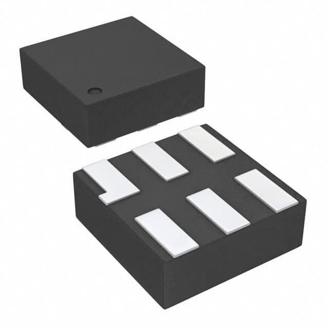
- Package: Surface Mount
- Essence: Single Buffer/Driver
- Packaging/Quantity: Tape and Reel, 3000 units per reel
Specifications
- Supply Voltage Range: 1.65V to 5.5V
- Input Voltage Range: 0V to VCC
- Output Voltage Range: 0V to VCC
- High-Level Input Voltage: 0.7 x VCC
- Low-Level Input Voltage: 0.3 x VCC
- High-Level Output Voltage: 0.9 x VCC
- Low-Level Output Voltage: 0.1 x VCC
- Maximum Operating Frequency: 80 MHz
- Propagation Delay: 4.2 ns (typical)
- Input Capacitance: 3 pF (typical)
- Output Capacitance: 6 pF (typical)
Detailed Pin Configuration
The SN74LVC1G240DSFR has a total of 6 pins:
- GND (Ground): Connected to the ground reference of the circuit.
- VCC (Supply Voltage): Connected to the positive supply voltage.
- A (Input): Input pin for the logic signal.
- Y (Output): Output pin for the logic signal.
- OE (Output Enable): Controls the output state.
- NC (No Connection): Pin not connected internally.
Functional Features
- Single buffer/driver with 3-state output.
- Compatible with various logic families due to wide supply voltage range.
- Supports bidirectional data flow.
- Provides high-speed operation with low power consumption.
- Offers protection against electrostatic discharge (ESD).
Advantages and Disadvantages
Advantages: - Wide supply voltage range allows compatibility with different systems. - Low power consumption enhances energy efficiency. - High-speed operation enables quick data processing. - ESD protection ensures reliability in harsh environments.
Disadvantages: - Limited number of inputs and outputs. - Not suitable for high-current applications. - May require additional components for specific circuit configurations.
Working Principles
The SN74LVC1G240DSFR is a single buffer/driver that operates on CMOS technology. It acts as an interface between the input signal and the output load, providing amplification and level shifting capabilities. The device can be enabled or disabled using the OE pin, allowing control over the output state. When enabled, the logic signal at the input (A) is amplified and transmitted to the output (Y). In the disabled state, the output is in a high-impedance state, effectively disconnecting it from the circuit.
Detailed Application Field Plans
The SN74LVC1G240DSFR finds applications in various fields, including:
- Consumer Electronics: Used in smartphones, tablets, and portable devices for signal amplification and level shifting.
- Automotive: Employed in automotive electronics for interfacing sensors, switches, and actuators.
- Industrial Automation: Integrated into control systems for signal conditioning and driving peripheral devices.
- Communication Systems: Utilized in networking equipment and data transmission circuits for signal buffering and conversion.
- Medical Devices: Incorporated into medical instruments for signal processing and interfacing with sensors.
Detailed and Complete Alternative Models
- SN74LVC1G07DBVR: Single Buffer/Driver with Open-Drain Output
- SN74LVC1G17DCKR: Single Schmitt-Trigger Buffer/Driver
- SN74LVC1G125DBVR: Single Bus Buffer/Driver with 3-State Output
- SN74LVC1G04DCKR: Single Inverter Gate
These alternative models offer similar functionality and characteristics, providing options for different design requirements.
Word count: 529 words
Seznam 10 běžných otázek a odpovědí souvisejících s aplikací SN74LVC1G240DSFR v technických řešeních
Sure! Here are 10 common questions and answers related to the application of SN74LVC1G240DSFR in technical solutions:
Q1: What is SN74LVC1G240DSFR? A1: SN74LVC1G240DSFR is a single buffer/driver with 3-state output, designed for use in various digital applications.
Q2: What is the voltage range supported by SN74LVC1G240DSFR? A2: SN74LVC1G240DSFR supports a voltage range from 1.65V to 5.5V.
Q3: What is the maximum output current of SN74LVC1G240DSFR? A3: The maximum output current of SN74LVC1G240DSFR is typically 32mA.
Q4: Can SN74LVC1G240DSFR be used as a level shifter? A4: Yes, SN74LVC1G240DSFR can be used as a level shifter to convert signals between different voltage levels.
Q5: What is the maximum propagation delay of SN74LVC1G240DSFR? A5: The maximum propagation delay of SN74LVC1G240DSFR is typically 4.3ns.
Q6: Is SN74LVC1G240DSFR compatible with both CMOS and TTL logic levels? A6: Yes, SN74LVC1G240DSFR is compatible with both CMOS and TTL logic levels.
Q7: Can SN74LVC1G240DSFR be used in battery-powered applications? A7: Yes, SN74LVC1G240DSFR is suitable for battery-powered applications due to its low power consumption.
Q8: Does SN74LVC1G240DSFR have built-in ESD protection? A8: Yes, SN74LVC1G240DSFR has built-in ESD protection to safeguard against electrostatic discharge.
Q9: Can SN74LVC1G240DSFR drive capacitive loads? A9: Yes, SN74LVC1G240DSFR can drive capacitive loads up to a certain limit specified in the datasheet.
Q10: What is the package type of SN74LVC1G240DSFR? A10: SN74LVC1G240DSFR is available in a small SOT-23 package, which is suitable for space-constrained applications.
Please note that these answers are general and may vary depending on the specific application and conditions. It's always recommended to refer to the datasheet and consult with technical experts for accurate information.