

Viz Specifikace pro podrobnosti o produktu.
SN74LVC240ADBR
Product Overview
- Category: Integrated Circuit
- Use: Logic Gate Buffer/Driver
- Characteristics: Low Voltage, CMOS Technology
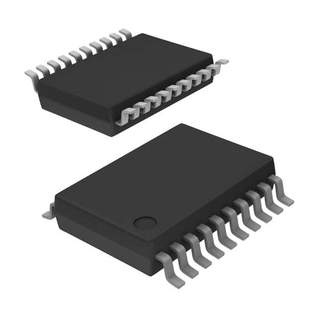
- Package: SSOP (Shrink Small Outline Package)
- Essence: Buffer/Driver for Digital Signals
- Packaging/Quantity: Tape and Reel, 2500 pieces per reel
Specifications
- Supply Voltage Range: 1.65V to 3.6V
- Input Voltage Range: 0V to VCC
- Output Voltage Range: 0V to VCC
- Maximum Operating Frequency: 80 MHz
- Number of Inputs: 8
- Number of Outputs: 8
- Propagation Delay Time: 4.2 ns (typical)
Detailed Pin Configuration
The SN74LVC240ADBR has a total of 20 pins. The pin configuration is as follows:
- A1 - Input 1
- Y1 - Output 1
- A2 - Input 2
- Y2 - Output 2
- GND - Ground
- A3 - Input 3
- Y3 - Output 3
- A4 - Input 4
- Y4 - Output 4
- VCC - Power Supply
- OE - Output Enable
- Y5 - Output 5
- A5 - Input 5
- Y6 - Output 6
- A6 - Input 6
- Y7 - Output 7
- A7 - Input 7
- Y8 - Output 8
- A8 - Input 8
- GND - Ground
Functional Features
- Buffer/Driver: The SN74LVC240ADBR acts as a buffer/driver for digital signals, ensuring proper signal strength and integrity.
- Low Voltage: It operates at a low voltage range of 1.65V to 3.6V, making it suitable for low-power applications.
- CMOS Technology: The integrated circuit is built using Complementary Metal-Oxide-Semiconductor (CMOS) technology, providing high noise immunity and low power consumption.
Advantages and Disadvantages
Advantages: - Low voltage operation allows for energy-efficient designs. - CMOS technology provides excellent noise immunity. - Compact SSOP package saves board space.
Disadvantages: - Limited maximum operating frequency compared to some other ICs. - May not be suitable for high-speed applications.
Working Principles
The SN74LVC240ADBR functions as a buffer/driver by amplifying and shaping digital signals. It takes input signals from the A1-A8 pins and provides amplified output signals on the Y1-Y8 pins. The OE pin controls the output enable/disable functionality.
Detailed Application Field Plans
The SN74LVC240ADBR can be used in various applications, including but not limited to: - Microcontrollers and microprocessors - Communication systems - Data transmission and reception - Signal buffering and level shifting - Industrial automation - Consumer electronics
Detailed and Complete Alternative Models
Some alternative models that offer similar functionality to the SN74LVC240ADBR are: - SN74LVC244A: Octal Buffer/Driver with 3-State Outputs - SN74LVC541A: Octal Buffer/Driver with 3-State Outputs - SN74LVC1G07: Single Buffer/Driver with Open-Drain Output
These alternative models provide different pin configurations, package options, or additional features, allowing designers to choose the most suitable option for their specific requirements.
Word count: 399 words
Seznam 10 běžných otázek a odpovědí souvisejících s aplikací SN74LVC240ADBR v technických řešeních
Sure! Here are 10 common questions and answers related to the application of SN74LVC240ADBR:
Q: What is SN74LVC240ADBR? A: SN74LVC240ADBR is a specific type of integrated circuit (IC) known as an octal buffer/line driver. It is commonly used in digital systems for signal buffering and driving applications.
Q: What is the voltage supply range for SN74LVC240ADBR? A: The voltage supply range for SN74LVC240ADBR is typically between 1.65V and 3.6V.
Q: How many input/output pins does SN74LVC240ADBR have? A: SN74LVC240ADBR has 8 input pins and 8 output pins, making it an octal buffer.
Q: What is the maximum output current that SN74LVC240ADBR can drive? A: SN74LVC240ADBR can typically drive up to 32mA of output current per channel.
Q: Can SN74LVC240ADBR be used for level shifting between different voltage domains? A: Yes, SN74LVC240ADBR can be used for level shifting as it supports bidirectional voltage translation between different voltage levels.
Q: Is SN74LVC240ADBR compatible with both CMOS and TTL logic levels? A: Yes, SN74LVC240ADBR is compatible with both CMOS and TTL logic levels, making it versatile for various digital systems.
Q: Does SN74LVC240ADBR have any built-in protection features? A: Yes, SN74LVC240ADBR has built-in ESD (electrostatic discharge) protection, which helps protect the IC from damage due to static electricity.
Q: Can SN74LVC240ADBR be used in high-speed applications? A: Yes, SN74LVC240ADBR is designed for high-speed operation and can typically support data rates up to 80Mbps.
Q: What is the typical propagation delay of SN74LVC240ADBR? A: The typical propagation delay of SN74LVC240ADBR is around 4.3ns.
Q: Are there any specific layout considerations when using SN74LVC240ADBR? A: Yes, it is recommended to follow proper PCB layout guidelines, such as minimizing trace lengths, providing adequate decoupling capacitors, and ensuring proper grounding, to optimize the performance of SN74LVC240ADBR.
Please note that the answers provided here are general and may vary depending on specific datasheet specifications and application requirements.