

Viz Specifikace pro podrobnosti o produktu.
SN74LVC821APWR
Product Overview
- Category: Integrated Circuit (IC)
- Use: Logic Gate
- Characteristics: Low Voltage, Very High-Speed CMOS (Complementary Metal-Oxide-Semiconductor) technology
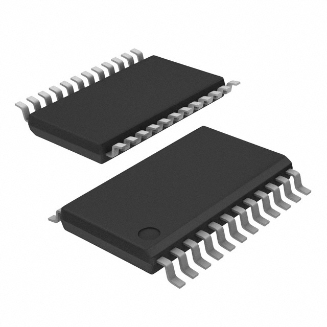
- Package: TSSOP (Thin Shrink Small Outline Package)
- Essence: 8-bit D-type Flip-Flop with 3-State Outputs
- Packaging/Quantity: Tape and Reel, 2500 pieces per reel
Specifications
- Supply Voltage Range: 1.65V to 5.5V
- Input Voltage Range: -0.5V to VCC + 0.5V
- Output Voltage Range: 0V to VCC
- Operating Temperature Range: -40°C to 85°C
- Propagation Delay Time: 2.7ns (typical)
- Output Drive Capability: ±24mA
- Power Dissipation: 4.6mW (typical)
Detailed Pin Configuration
The SN74LVC821APWR has a total of 20 pins. The pin configuration is as follows:
- CLR (Clear)
- D0 (Data Input 0)
- D1 (Data Input 1)
- D2 (Data Input 2)
- D3 (Data Input 3)
- D4 (Data Input 4)
- D5 (Data Input 5)
- D6 (Data Input 6)
- D7 (Data Input 7)
- GND (Ground)
- Q0 (Flip-Flop Output 0)
- Q1 (Flip-Flop Output 1)
- Q2 (Flip-Flop Output 2)
- Q3 (Flip-Flop Output 3)
- Q4 (Flip-Flop Output 4)
- Q5 (Flip-Flop Output 5)
- Q6 (Flip-Flop Output 6)
- Q7 (Flip-Flop Output 7)
- OE (Output Enable)
- VCC (Power Supply)
Functional Features
- 8-bit D-type flip-flop with 3-state outputs
- Clear input (CLR) for synchronous reset of all flip-flops
- Output enable input (OE) to control the outputs
- High-speed operation with low power consumption
- Compatible with TTL (Transistor-Transistor Logic) and CMOS logic levels
- Schmitt-trigger inputs for noise immunity
- Balanced propagation delays for accurate timing
Advantages and Disadvantages
Advantages: - Low voltage operation allows for compatibility with a wide range of systems - Very high-speed operation enables efficient data processing - 3-state outputs provide flexibility in connecting multiple devices - Schmitt-trigger inputs ensure reliable operation in noisy environments
Disadvantages: - Limited output drive capability may restrict use in certain applications requiring higher current sourcing/sinking - Temperature range limited to -40°C to 85°C, which may not be suitable for extreme temperature environments
Working Principles
The SN74LVC821APWR is an 8-bit D-type flip-flop with 3-state outputs. It operates based on the principles of digital logic. The flip-flop stores and transfers data using clock signals. The clear input (CLR) allows for synchronous reset of all flip-flops, while the output enable input (OE) controls the outputs. The device operates at low voltages and utilizes CMOS technology for high-speed and low-power performance.
Detailed Application Field Plans
The SN74LVC821APWR can be used in various applications, including but not limited to:
- Microprocessor-based systems
- Data storage and retrieval systems
- Communication systems
- Industrial control systems
- Automotive electronics
- Consumer electronics
Detailed and Complete Alternative Models
- SN74LVC821ADW - SOIC (Small Outline Integrated Circuit) package, tube packaging
- SN74LVC821APW - TSSOP package, tube packaging
- SN74LVC821ARGYR - VQFN (Very Thin Quad Flat No-Lead) package, tape and reel packaging
- SN74LVC821APWT - TSSOP package, tape and reel packaging
- SN74LVC821APWTE4 - TSSOP package, tape and reel packaging, RoHS compliant
These alternative models offer similar functionality and characteristics to the SN74LVC821APWR, providing options for different packaging preferences or specific application requirements.
Word count: 530 words
Seznam 10 běžných otázek a odpovědí souvisejících s aplikací SN74LVC821APWR v technických řešeních
Sure! Here are 10 common questions and answers related to the application of SN74LVC821APWR:
Q: What is the SN74LVC821APWR? A: The SN74LVC821APWR is a high-performance, low-voltage CMOS 10-bit bus interface flip-flop with 3-state outputs.
Q: What is the operating voltage range for the SN74LVC821APWR? A: The operating voltage range is from 1.65V to 3.6V.
Q: What is the maximum clock frequency supported by the SN74LVC821APWR? A: The maximum clock frequency is 100 MHz.
Q: How many flip-flops are there in the SN74LVC821APWR? A: There are 10 flip-flops in total.
Q: Can I use the SN74LVC821APWR in both parallel and serial data transfer applications? A: Yes, the SN74LVC821APWR can be used in both parallel and serial data transfer applications.
Q: What is the output drive capability of the SN74LVC821APWR? A: The output drive capability is ±24 mA.
Q: Does the SN74LVC821APWR have internal pull-up or pull-down resistors? A: No, the SN74LVC821APWR does not have internal pull-up or pull-down resistors.
Q: Is the SN74LVC821APWR compatible with other logic families? A: Yes, the SN74LVC821APWR is compatible with TTL, LVTTL, and LVCMOS logic families.
Q: What is the typical propagation delay of the SN74LVC821APWR? A: The typical propagation delay is 3.5 ns.
Q: Can I use the SN74LVC821APWR in automotive applications? A: Yes, the SN74LVC821APWR is qualified for automotive applications and meets the AEC-Q100 standard.
Please note that these answers are general and may vary depending on the specific datasheet and application requirements.