

Viz Specifikace pro podrobnosti o produktu.
UCC2804PWTR
Basic Information Overview
- Category: Integrated Circuit (IC)
- Use: Power Management
- Characteristics: PWM Controller
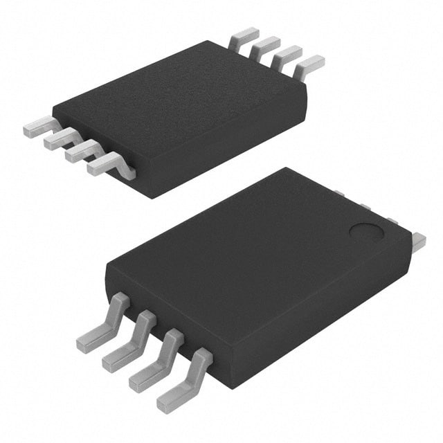
- Package: TSSOP-14
- Essence: Voltage Mode PWM Controller
- Packaging/Quantity: Tape and Reel, 2500 units per reel
Specifications
- Input Voltage Range: 8V to 35V
- Output Voltage Range: 0V to 5.1V
- Operating Temperature Range: -40°C to +85°C
- Frequency Range: 50kHz to 1MHz
- Duty Cycle Range: 0% to 100%
- Maximum Output Current: 200mA
- Quiescent Current: 2.5mA
Detailed Pin Configuration
- VREF: Reference Voltage Input
- COMP: Error Amplifier Output
- FB: Feedback Input
- RT/CT: Timing Components Connection
- GND: Ground
- CS: Current Sense Input
- SS/TR: Soft-Start/Shutdown Control
- VCC: Supply Voltage Input
- OUT: PWM Output
- NC: No Connection
- NC: No Connection
- NC: No Connection
- NC: No Connection
- NC: No Connection
Functional Features
- Voltage mode control with adjustable duty cycle
- Internal error amplifier for precise regulation
- Soft-start and shutdown control
- Overcurrent protection
- Undervoltage lockout
- Thermal shutdown protection
Advantages
- Wide input voltage range allows for versatile applications
- Adjustable duty cycle provides flexibility in power management
- Internal error amplifier ensures accurate regulation
- Soft-start feature prevents excessive inrush current
- Overcurrent protection enhances system safety
- Undervoltage lockout protects against low input voltage conditions
- Thermal shutdown prevents IC damage due to excessive heat
Disadvantages
- Limited maximum output current may restrict certain high-power applications
- TSSOP-14 package may require careful handling during assembly
Working Principles
The UCC2804PWTR is a voltage mode PWM controller that regulates the output voltage by adjusting the duty cycle of the PWM signal. It compares the feedback voltage (FB) with the reference voltage (VREF) and generates an error signal. This error signal is amplified by the internal error amplifier and compared with the ramp signal generated by the timing components (RT/CT). The resulting PWM signal controls the power switch, which in turn regulates the output voltage.
Detailed Application Field Plans
The UCC2804PWTR is commonly used in various power management applications, including: 1. Switching Power Supplies 2. DC-DC Converters 3. LED Drivers 4. Battery Chargers 5. Motor Control Circuits
Detailed and Complete Alternative Models
- UCC2804N
- UCC2804D
- UCC2804QDRQ1
- UCC2804PW
- UCC2804PWR
Note: These alternative models have similar specifications and pin configurations but may differ in package type or other minor features.
This entry provides an overview of the UCC2804PWTR, a voltage mode PWM controller used in power management applications. It includes basic information, specifications, pin configuration, functional features, advantages and disadvantages, working principles, application field plans, and alternative models.
Seznam 10 běžných otázek a odpovědí souvisejících s aplikací UCC2804PWTR v technických řešeních
Sure! Here are 10 common questions and answers related to the application of UCC2804PWTR in technical solutions:
Q: What is UCC2804PWTR?
A: UCC2804PWTR is a pulse width modulation (PWM) controller IC commonly used in power supply applications.Q: What is the operating voltage range of UCC2804PWTR?
A: The operating voltage range of UCC2804PWTR is typically between 8V and 35V.Q: What is the maximum switching frequency supported by UCC2804PWTR?
A: UCC2804PWTR can support a maximum switching frequency of up to 500kHz.Q: Can UCC2804PWTR be used in both buck and boost converter topologies?
A: Yes, UCC2804PWTR can be used in both buck and boost converter topologies.Q: Does UCC2804PWTR have built-in protection features?
A: Yes, UCC2804PWTR has built-in protection features such as overcurrent protection and thermal shutdown.Q: What is the typical output current capability of UCC2804PWTR?
A: The typical output current capability of UCC2804PWTR is around 200mA.Q: Can UCC2804PWTR operate in continuous or discontinuous conduction mode?
A: UCC2804PWTR can operate in both continuous and discontinuous conduction modes.Q: Is UCC2804PWTR suitable for high-efficiency power supply designs?
A: Yes, UCC2804PWTR is suitable for high-efficiency power supply designs due to its low power consumption and high switching frequency capability.Q: Can UCC2804PWTR be used in offline power supply applications?
A: Yes, UCC2804PWTR can be used in offline power supply applications with appropriate isolation and safety measures.Q: Are there any application notes or reference designs available for UCC2804PWTR?
A: Yes, Texas Instruments provides application notes and reference designs for UCC2804PWTR, which can help in designing power supplies using this IC.
Please note that the answers provided here are general and may vary depending on specific design requirements and application scenarios. It is always recommended to refer to the datasheet and relevant documentation for accurate information.