

Viz Specifikace pro podrobnosti o produktu.
IRF614 Transistor: Encyclopedia Entry
Introduction
The IRF614 transistor is a crucial component in the field of electronics and electrical engineering. This encyclopedia entry aims to provide a comprehensive overview of the IRF614 transistor, including its product category, basic information, specifications, pin configuration, functional features, advantages and disadvantages, working principles, application field plans, and alternative models.
Product Category and Basic Information Overview
- Category: Power MOSFET Transistor
- Use: The IRF614 transistor is commonly used as a switching device in various electronic circuits, particularly in power supply applications.
- Characteristics: It exhibits high voltage capability, low on-state resistance, and fast switching speed.
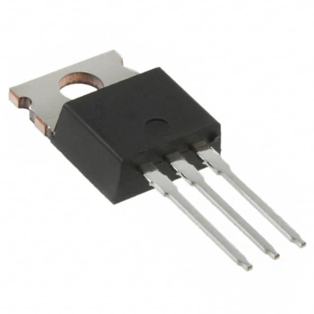
- Package: TO-220AB package
- Essence: The essence of the IRF614 lies in its ability to efficiently control and regulate power flow within electronic systems.
- Packaging/Quantity: Typically available in reels or tubes containing multiple units.
Specifications
- Voltage Rating: 250V
- Current Rating: 8A
- On-State Resistance (RDS(on)): 0.85Ω
- Power Dissipation: 125W
- Operating Temperature Range: -55°C to 175°C
Detailed Pin Configuration
The IRF614 transistor features a standard TO-220AB package with three leads: 1. Gate (G): Input terminal for controlling the switching operation. 2. Drain (D): Output terminal connected to the load. 3. Source (S): Common terminal connected to the ground or reference potential.
Functional Features
- High Voltage Capability: The IRF614 can withstand high voltage levels, making it suitable for power applications.
- Low On-State Resistance: This feature minimizes power losses and enhances efficiency during conduction.
- Fast Switching Speed: Enables rapid transition between on and off states, facilitating efficient power regulation.
Advantages and Disadvantages
Advantages
- High voltage rating suitable for power applications
- Low on-state resistance for reduced power losses
- Fast switching speed for efficient power regulation
Disadvantages
- Relatively higher gate capacitance may require careful driver circuit design
- Sensitivity to static electricity and overvoltage conditions
Working Principles
The IRF614 operates based on the principle of field-effect transistors (FETs), where the flow of current between the drain and source terminals is controlled by the voltage applied to the gate terminal. When a sufficient gate-source voltage is applied, the transistor enters the conducting state, allowing current to flow from the drain to the source.
Detailed Application Field Plans
The IRF614 transistor finds extensive use in various applications, including: - Switching Power Supplies: Utilized in DC-DC converters and voltage regulation circuits. - Motor Control: Employed in motor drive circuits for controlling speed and direction. - Electronic Ballasts: Used in fluorescent lamp ballast circuits for efficient energy conversion.
Detailed and Complete Alternative Models
Several alternative models to the IRF614 transistor include: - IRF610: Similar characteristics with a lower voltage rating - IRF620: Higher voltage and current ratings for more demanding applications - IRFZ44N: Enhanced switching speed and lower on-state resistance
In conclusion, the IRF614 transistor serves as a vital component in power electronics, offering high voltage capability, low on-state resistance, and fast switching speed. Its application spans across various fields, from power supplies to motor control, making it an indispensable element in modern electronic systems.
Word Count: 536
Seznam 10 běžných otázek a odpovědí souvisejících s aplikací IRF614 v technických řešeních
What is the IRF614 transistor used for?
- The IRF614 is a power MOSFET transistor commonly used in high-power switching applications such as motor control, power supplies, and inverters.
What are the key specifications of the IRF614?
- The IRF614 has a maximum drain-source voltage (Vds) of 250V, a continuous drain current (Id) of 3.3A, and a low on-resistance (Rds(on)) of 0.75 ohms.
How do I properly drive the IRF614 in my circuit?
- To drive the IRF614 effectively, ensure that the gate voltage exceeds the threshold voltage (typically around 4V) to fully turn on the transistor. Use appropriate gate drivers to achieve fast switching and minimize power dissipation.
Can the IRF614 be used for PWM (Pulse Width Modulation) applications?
- Yes, the IRF614 is suitable for PWM applications due to its fast switching characteristics and low Rds(on), making it efficient for controlling power delivery in variable speed drives and other PWM-based systems.
What are the typical thermal considerations when using the IRF614?
- It's important to consider heat dissipation and use proper heatsinking to maintain the transistor within its safe operating temperature range, especially in high-power applications.
Are there any common failure modes associated with the IRF614?
- Common failure modes include overvoltage or overcurrent conditions leading to thermal stress, which can cause the transistor to fail. Proper protection circuits and derating guidelines should be followed to prevent these failures.
Can the IRF614 be used in automotive applications?
- Yes, the IRF614 can be used in automotive applications such as motor control, lighting systems, and power distribution, provided it meets the necessary automotive standards and requirements.
What are some alternative transistors to the IRF614?
- Alternative transistors with similar characteristics to the IRF614 include the IRF510, IRF540, and IRF640, which can be considered based on specific application requirements.
How do I calculate the power dissipation in the IRF614?
- Power dissipation can be calculated using the formula P = I^2 * Rds(on), where I is the drain current and Rds(on) is the on-resistance of the transistor.
What precautions should be taken when soldering the IRF614 onto a PCB?
- When soldering the IRF614 onto a PCB, it's important to follow proper ESD (electrostatic discharge) handling procedures and adhere to recommended soldering temperatures and techniques to avoid damaging the transistor during assembly.